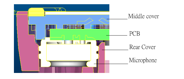
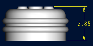
1. mic : 2.85 ±0.2
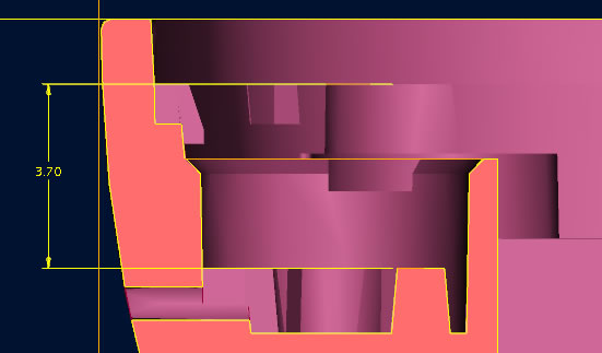
2. Rear Cover : 3.7 ±0.1
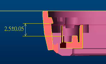
3. Real cover of mic hole bottom to hook distance is 2.5 ±0.05
4. Middle cover and rear cover hook distance is 0 .
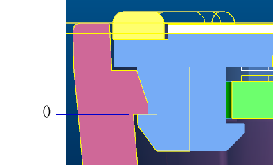
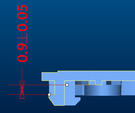
5. Middle cover of Hook to base on PCB boss distance is 0.9 ±0.05
6. Pcb thickness is 1.0 ±0.1 mm
Verify
Tolerance analysis report: TA_10012008
Analysis
Worst Case : Gap Max= 2.4+0.2=2.6 mm Min=2.4-0.2=2.2 mm
Statistical : Gap Max=2.4+0.12=2.52mm Min=2.4-0.12=2.28 mm
Because microphone compressed working height is 2.45 ±0.1 mm , and general condition that cell phone has increase height from as around some components forced or deform caused mic contact pcb trend for bigger space , So it can consider actually measure pcb and mic hole bottom distance as critical over normal dimension 2.43 mm (Mean).
Think assembly relationship
1.Mic put on Rear Cover
2. pcb put on middle cover
3. Middle cover sub assemble into the Rear Cover sub assembly
So loop is
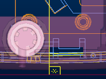
Pcb pad center-> Pcb hole center ->pcb hole of radius -> Pcb hole and middle cover boss of gap -> middle cover boss of radius ->middle cover boss center -> Rear cover boss center -> D Cover mic hole center
About Y axis
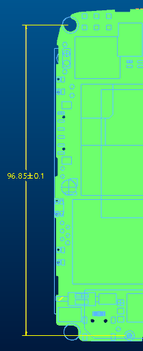
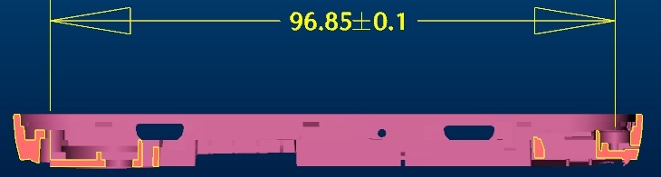
1.Pcb pad center and Pcb hole center distance is 96.85 ±0.1 mm
2. Pcb hole of radius is R2±0.05
3. Pcb hole and middle cover boss of gap
Gap=R2-R1.87=0.13
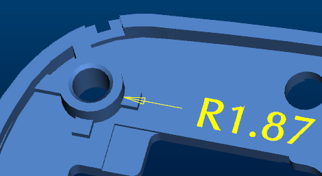
4. middle cover boss of radius is R1.87 ±0.05 mm
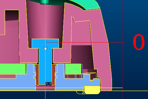
5.Middle cover boss center to Rear cover boss center distance is 0 mm
6. Rear cover boss center to Rear cover mic hole center by Y axis is 96.85 ± 0.1 mm
Verify
Tolerance analysis report: TA_10032008
Pro/E CETOL analysis : Report
Analysis
Worst Case : Mic center shift = ± 0.3 mm
Statistical : Mic center shift = ± 0.16 mm
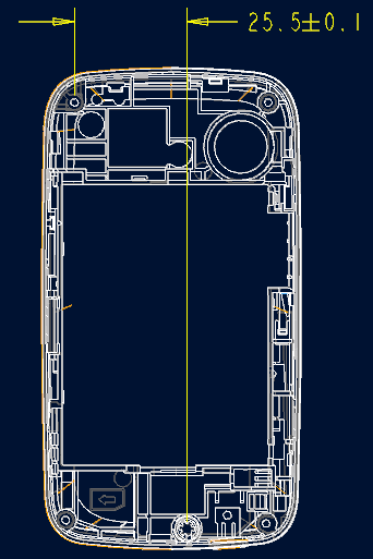
About X axis
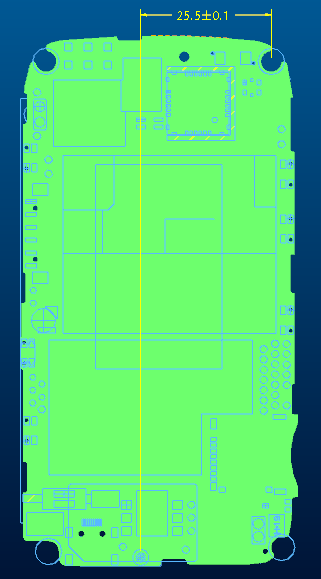
1.Pcb pad center and Pcb hole center distance is 25.5 ± 0.1 mm
2. Pcb hole of radius is R2±0.05 mm
3. Pcb hole and middle cover boss of gap is 0.13 mm
4. middle cover boss of radius is R1.87 ±0.05 mm
5.Middle cover boss center to Rear cover boss center distance is 0 mm
6. Rear cover boss center to Rear cover mic hole center by X axis is 25.5 ± 0.1 mm
Verify
Tolerance analysis report: TA_10062008
Analysis
Worst Case : Mic center shift = ± 0.3 mm
Statistical : Mic center shift = ± 0.16 mm
Conclusion