|
|
|
PRO/ENGINEER
2003年第二季軟體技術文件
2003/04/01
Be Flexible in Wildfire
Flexible Components is a new function in Pro/ENGINEER Wildfire that gives users
added capabilities for assembly management. The Make Flexible command allows
users to change solid objects into flexible objects existing in different states
inside an assembly. Each occurrence of the component can have a different
flexibility assigned to it, and it will only show up as one BOM item. Having
this capability eliminates the need for multiple unique object numbers for a
single object displayed in different states. Prior to Wildfire, it was necessary
to create unique objects or family tables when attempting to display the same
spring in different states of compression in the same assembly. This added extra
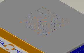
items to the BOM and required a manual change to correct. Figure 1 shows
five uncompressed springs assembled to holes in a circular housing. The four
springs around the outer surface of the housing are sitting on washers that are
located in the middle of each hole.
Figure 1
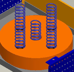
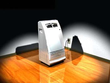
The center spring is located in a hole that has no washer, so it rests on the
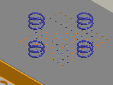
surface of the chassis to which the housing is assembled. When the cover of the
chassis is installed, the four springs will protrude through the top of the
cover while the fifth spring (fully uncompressed) just touches the inside of the
top cover. (See Figure 2.)
Figure 2
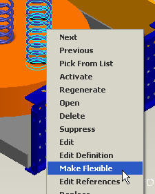
Compressing the four springs that are assembled to the outer holes on the
housing so that they just touch the inside of the top cover, can be accomplished
in Wildfire by making the springs "Flexible" components. Highlight one of the
springs that you wish to compress and click your right-mouse button. Select
Make Flexible from the pop-up menu. (See Figure 3.)
Figure 3
The Varied Items dialog box will appear. (See Figure 4.)
Figure 4
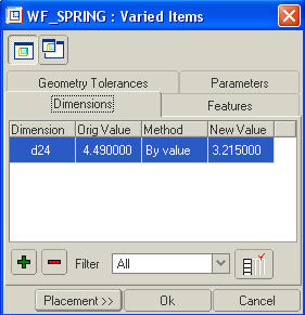
Select the green add button and use the Search Tool to find the
dimension in the spring that will allow it to be compressed. Select Apply
and select OK from the Select box. The dimension you selected will be
visible in the Varied Items box. (See Figure 5.)
Figure 5
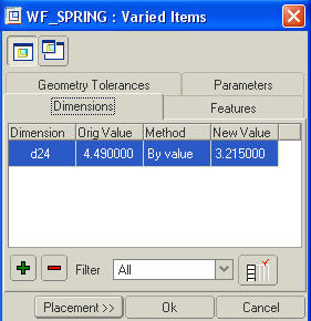
Change New Value to allow the spring to just touch the inside of the top
cover and select Placement from the Varied Items dialog box. The
Component Placement dialog box will appear with a new button called Define
Flexibility. This button allows you to go back and modify the flexibility values
(varied items) of the spring. Select OK from the Component Placement
dialog box to complete the operation. The springs should be completely inside
the top cover, as shown in Figure 6.
Figure 6
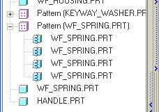
Inside the model tree, the four springs will have a new icon attached to them
indicating that they are flexible components. (See Figure 7.)
Figure 7
--Submitted by Stan Balish, president and chief executive officer, FroTime
Inc., San Diego, CA
How to Flatten a Harness Without the Network
(This tip can be applied in Wildfire in the Harness-MFG module.)
In previous releases, harness networks were flattened automatically with the
wires, cables or bundles in a flattened harness. The only way to remove the
network was to blank on a layer.
In Pro/ENGINEER Wildfire, the config.pro option "fan_with_network" has been
added and may be set to NO (default is YES) to exclude the network
from being flattened.
--Submitted by Florin Neamtu, principal engineer, PTC technical support,
Needham, MA
Determine What Materials to Use
When parts are in the early development stages, it is not always clear which
material to use. For example, 50 percent long glass polypropylene has a
different performance characteristic and density than 20 percent short glass.
Rather than modifying the Pro/ENGINEER part's density every time you want to
look at its total weight, you can write a relation to maintain as many options
as you wish. See below:
weight_material_1 = density * mp_volume("")
weight_material_2 = density * mp_volume("")
Substitute the material name and density values as needed. The "weight_material_*"
parameter then can be displayed as a parametric note on a drawing or used for
further calculations.
--Submitted by Steven J. Frey, vice president, Universal Parametrics, Inc.,
Ann Arbor, MI
Show a Mechanism Position on a Drawing
Under Drag Dialog, snapshot the mechanism position. Use the
make-available-in-drawing icon to make the snapshot visible in the drawing.
Create a new view or modify an existing view. Set the type as exploded. The
mechanism snapshots will be listed as an exploded state.
--Submitted by Ian Turner, design application support, CSC, MBDA UK Account,
Stevenage, UK
Drawing Snap Lines
Use snap lines to expedite drawing cleaning. A snap line is a line that shows up
on the screen but not on the printed drawing. It allows you to line up balloons,
notes or any draft entities that can be moved using the normal move command.
When an entity is selected and moved near the snap line, it snaps to it.
The moved entity will change colors when it is attached to the snap line. By
using the snap line, balloons can be lined up perfectly straight. The figure
below shows several balloons lined up on two snap lines.
Snap lines can be defined on individual drawings to locate dimensions, notes,
geometric tolerances, symbols and surface finishes. The system positions the
snap lines relative to the view outline, a selected model edge or datum plane.
After you place an item on a snap line, the item moves if the grid line moves
(such as when the view outline expands).
When placing and locating items on snap lines, keep the following two points in
mind:
- When you move an item onto one snap line, its color changes to magenta. If
you set the location by pressing the left-mouse button, the item snaps to the
snap line. Until you move the item again, the snap line determines its
location.
- If you move an item onto the intersection of two snap lines, the system
highlights one of the lines in red. If it snaps that item to more than one set
of snap lines at that location, you can navigate all possible sets using the
SEL SNAP LINE menu. When you choose Accept, the system locates the item on the
intersection of the two snap lines. When you move either snap line, the item
moves with it.
To Create a Snap Line:
- Select Insert >Snap Line on the menu bar.
- On the Menu Manager, do one of the following:
 | Choose CR SN LINE >Att View. Select a view border and
specify the offset from the border and the number of lines to create. If you
are creating more than one line, specify the space between the two lines. The
snap line attaches to the specified view border. |
| Choose CR SN LINE >Att Geom/Snap. Select view geometry (such as an
edge), a datum plane or another snap line. Specify values for the offset, the
number of lines to create and the space between the two lines (if you are
creating more than one line). The snap lines attach to the specified view
geometry, datum plane or snap line. |
You can snap an item to one snap line or to the intersection of two snap
lines. You can also attach clipped detail entities such as dimensions, witness
line endpoints, set datum endpoints and axis endpoints.
You can place the following items on snap lines:
| Dimensions |
| Clipped dimension arrows |
| Notes |
| Symbols |
| Set datum names |
| Set datum line endpoints |
| Geometric tolerances |
| Surface finishes |
| View arrows |
| Balloons |
--Submitted by Sayeeprasad G., engineering assistant, Miller Fluid Heads,
Artarmon, Australia
Automating Pro/E, Pro/INTRALINK Installation
Here is a not-so-well-documented technique that enables you to:
| Automate your Pro/E and Pro/INTRALINK installation. |
| Use PTC.Setup trail files. |
| Record every click and entry you make in the setup program and
automatically replay the steps for each new Pro/E installation. |
This will save a lot of time and prevent you from having to be at the
computer to make the right picks. Here are the details:
| Run your setup with the option -uilog on the command line: ptcsetup -uilog.
|
| Perform all the selections needed for a standard installation including
license servers, installation folder, etc. |
| The trail file ps_trl.txt.numeric suffix is created in the current folder.
Rename the trail file (for example, setup.txt) and place it in a convenient
place such as the bin folder. |
| Write a script to call setup within the trail file and place it in the
same folder: ptcsetup -uitrail setup.txt |
There also is the option of running setup without displaying on screen (use -nographics
option): ptcsetup -nographics -uitrail setup.txt.
See the PTC description in TPI 103331 for more information.
This technique is especially useful for installing Pro/INTRALINK. You could
incorporate it into your standard installation procedure so all new clients are
set up with the correct paths, servers, etc.
--Submitted by Edwin Muirhead, CAD systems administrator, Aberdeen, Scotland,
UK and
www.geocities.com/proehelp/index.html?admin.htm#setup
Response Pro/Clues 3 - Vol. 2, Issue 3
I would still have to be at the computer to log into it as an administrator and
to start the process. A user does not have rights to install most programs. How
can I get around this?
--Stephen Galayda, CAD system administrator assistant, HydraForce, Inc.,
Lincolnshire, IL
Sizing Pro/INTRALINK Columns
To get your Pro/INTRALINK columns to be only as big as needed, point your mouse
over the column heading and hit the right-mouse button. They will adjust
automatically, usually narrowing to the longest entry listed.
--Submitted by Sandy Buerkle, designer, Welch Allyn Inc., Skaneateles Falls,
NY
Response PRO/CLUES 4 - Vol. 2, Issue 3
In addition to resizing one column with a right-click:
| Hold down shift and right-click. This resizes the column and columns to
the right. This is useful for resizing all columns in the window. |
| Left-click to sort by column. |
| Hold down shift and left-click to add a second sort column. |
--Ed Muirhead, CAD systems administrator, Aberdeen, Scotland, UK.

2003/04/18
Q1- Vol. III, Issue 13
I am trying to model the shin guards (shown below) in Pro/ENGINEER, but I am
having trouble getting the shape to be correct. Can you recommend any advanced
tutorials or other training guides to help me solve this modeling problem?
--Andrew Walter, engineering student, Australian National University,
Canberra, ACT Australia
A1.1- Vol. III, Issue 13
The profile of the skin guard you show on the picture seems quite complex. It is
better to first digitize it using a laser digitizer or CMM. Afterward, bring the
digitized data into Pro/E.
--Yasir Arfeen, CAD/CAM engineer, OJ Pvt. Ltd., Karachi, Pakistan
A1.2- Vol. III, Issue 13
The best tutorials at student rates can be found at
www.frotime.com.
--G. Alexander Korentis, mechanical/biomedical engineer, QCI Engineering,
University of Connecticut, biomedical engineering doctoral student, Storrs, CT
A1.3- Vol. III, Issue 13
Take the "Advanced Surfacing Training" course offered by PTC or Rand.
--Chris Boyer, manager of product creation, Freudenberg Household Products
LP, Northlake, IL
A1.4- Vol. III, Issue 13
You might try looking into medical archives. If an FTP site exists for your
software, you may find proven applications there.
--Craig D. Skogerson, Indio, CA
Q2- Vol. III, Issue 13
I just received Pro/ENGINEER Wildfire and I am concerned about its stability. In
the past, I have heard it was wise to wait a few months before installing new
versions. Has anyone had problems with Wildfire and would you recommend I wait
until any possible bugs are worked out?
--Pascal Normand, designer, research and development, Industrial Handling
Division, IPL Inc., St-Damien, Quebec, Canada
A2.1- Vol. III, Issue 13
I've been using Wildfire for about a month and I have not come across any bugs
yet. I do stress yet. I have found it much better and easier to use than
R2001 once you get to know where everything is. An important addition is the
Menu Mapper under the Help menu. To find out how to do something in Wildfire,
open the Menu Mapper. The Menu Mapper shows an R2001 screen with the old-style
menu layout. After you run through the R2001 way of executing the command, using
the R2001 menus shown, the Menu Mapper will show you how to do it in Wildfire.
It is an excellent tool.
--Jeff Taylor, mechanical production engineer, Imagination Technologies Ltd.,
London, UK
A2.2- Vol. III, Issue 13
I installed Wildfire and just did my first real rush job with it. I took nine
hours nonstop and a large thermos of coffee. But I got it done. This was the
first time I used it. I have had no training on it. That speaks to its usability
and the fact that the interface has not changed a lot from the previous version.
However, Wildfire crashed four times doing routine tasks. Thankfully, no
critical steps were lost, and I was able to carry on. But it is definitely not
yet stable.
--Christopher J. Purcell, defense research and development, Canada Atlantic,
Dartmouth NS, Canada
A2.3- Vol. III, Issue 13
Wildfire does not work with Pro/INTRALINK.
--Tom Hargrove, fusion energy division, Oak Ridge National Laboratory, Oak
Ridge, TN
A2.4- Vol. III, Issue 13
You are right. Often it is better to wait for some builds after the first
production edition of a new Pro/E release. I have not tried Wildfire yet, but
I'll wait at least a couple of months before using it in a production
environment.
--Luca Armellin, mechanical engineer, Metelli SpA, Brescia, Italy
More Answers to Previous Questions
Q1- Vol. III, Issue 12
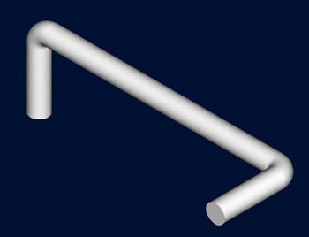
I have modeled a rod with two bends on two different planes. How do I unbend the
rod shown in the image below?
--Herb Spaulding, product engineer, Miller Industries, Ooltewah, TN
A1.1- Vol. III, Issue 12
Create a datum curve that follows the path you want. If it is a 2D path you want
to follow, you have to use the 2 Projections option in the Curve menu. Select
Insert >Datum >Curve and choose 2 Projections. If you choose two
datums at right angles to each other, they will create a datum curve where the
two intersect. You can then create a sweep. Select Create >Protrusion >Sweep
and choose Select Traj. Select the datum curve you have just selected and
sketch a round section. This technique can also be used to create sweeped pipes
in assemblies.
--Brian Middlemore, CAD support engineer, NCR Ltd., Dundee, Tayside, Scotland
Bar
Datum curve

A1.2- Vol. III, Issue 12
If you have modeled the rod with a toroidal bend tweak and you want to obtain a
straight workpiece, suppress the toroidal features.
--Zachary Popov, mechanical engineer, Technical University, Varna, Bulgaria
Q2- Vol. III, Issue 12
As of Pro/WILDFIRE, the internal datum plane, aka "on-the-fly" created datum
plane, functionality is removed. I am wondering if this will impair model
building?
--Alexander Fabre, B. Sc. M. E., Avalon Technology Stockholm AB, Sweden
A2.1- Vol. III, Issue 12
This functionality resides within the feature creation. While creating the
feature, click on the pause button at the bottom right of the screen. (It is
next to the preview button.) Create the necessary axes, planes, points etc, and
click on the pause button to continue building the feature. (Planes, axes,
points, etc. on the "fly").
--Roman Panov, MCAD application specialist, Engineering Data Resources AS,
Norway
A2.2- Vol. III, Issue 12
The "Make Datum" command is not necessarily removed, it has been restructured.
An "on-the-fly" datum still can be created by means of the same menu option for
creating a datum. The difference in Wildfire is that the "on-the-fly" datum
plane is an actual feature in the Model Tree and can be selected for reference
when creating other features. So "on-the-fly" datums are now more useful. The
only impairment is that users accustomed to the old menu selection have to learn
Wildfire's dashboard-style menu structure, which is easy to learn.
--Wes Gerber, mechanical design engineer, ITT Industries,
Aerospace/Communications Division, Fort Wayne, IN
A2.3- Vol. III, Issue 12
The internal datum plane functionality is not removed. It is accessed
differently. If you wish to create a datum on the fly, use the same icons or
menu picks as you would when creating "visible" datums. Datums created during
feature creation are listed in the model tree, but are automatically hidden and
grouped with the feature being created. In most cases the feature you are
creating - such as an extruded protrusion - will grab the plane you create and
use it for the sketching plane. If Wildfire does not select the created plane
automatically, then you can select it yourself. The important thing to note is
that on-the-fly datums are still with us.
--Kellie Wheatcroft, mechanical engineer, Smart Design, Perth, Western
Australia
Q1- Vol. III, Issue 12
I have modeled a rod with two bends on two different planes. How do I unbend the
rod shown in the image below?
--Herb Spaulding, product engineer, Miller Industries, Ooltewah, TN
A1.1- Vol. III, Issue 12
The model should be recreated with a straight rod and a datum curve defining the
shape you want the rod to become and then by using spinal bend. Another option
would be to create a sheet metal component of which an edge defines the
centerline of the rod. Create a datum curve that is a composite of the edge
defining the centerline. Create a solid swept protrusion that follows the curve.
Make the sheet metal component small enough to be buried within the rod. Then
flat-pattern the sheet metal portion to get your straight rod and suppress to
get the bent rod.
--Brian S. Lynn, design drafter/CAD administrator, Weil-McLain, Heating
America!, Indiana
A1.2- Vol. III, Issue 12
One way to handle this situation is to create the feature as a datum curve
instead of as a solid feature. You can create the path using two datum curves,
making sure to make a composite curve afterward. Create an extruded solid the
same length as your curves. (See Spinal Before image below.) Create a
spinal bend by selecting Feature >Create >Tweak >Spinal Bend. Work your
way through the menus and select the extrude material to bend around the
composite curve. When asked to select a plane to define the volume of bend,
select the opposing end of your extrusion to get the desired result. (See
Spinal After image below.) You can create an instance by removing the spinal
bend feature giving you both a "bent" and "unbent" form of your part. You can
also find an example of this by searching the help files using "spinal" as the
keyword.
--Greg Daniel N.D.G.A. systems analyst/MCAD administrator, SPACEHAB, Inc. /
Johnson Engineering, Webster, TX
Spinal Before
Spinal After
A1.3- Vol. III, Issue 12
Redefine your trajectory.
--Doug Rogers, project engineer - Fuel Metering Valves, Precision Engine
Controls Corp., San Diego, CA
A1.4- Vol. III, Issue 12
If the feature was not created by a trajectory protrusion, create a family table
that includes the bent feature. The new instance should have this feature set to
No. Include a feature that includes the dimension for the length and
modify that number to the correct length when the part is unbent. If it was
created by a trajectory protrusion, remodel it or these instructions will not
work.
--Karen Thacker, design engineer, Physitron Inc., Huntsville, AL
Q2- Vol. III, Issue 12
As of Pro/WILDFIRE, the "internal datum plane," aka "on the fly created datum
plane," functionality is removed. I am wondering if this will impair model
building?
--Alexander Fabre, B. Sc. M. E., Avalon Technology Stockholm AB, Sweden
A2.1- Vol. III, Issue 12
I called tech support about this question. They said to just use the Create
Datum Icon from the toolbar. It will still be a "datum on the fly". The
"Make Datum" menu pick is just not available anymore.
--Greg Morris, associate designer, The Halex Co., Bedford Heights, OH
A2.2- Vol. III, Issue 12
In Wildfire, you can still create datums "on the fly," but when you are finished
creating the feature you will have a group in your model tree that contains the
feature and the hidden datum planes. You can unhide these datums later and use
them for references for other features if you wish.
--Paul Bock, mechanical engineer, Plesh Industries, Inc., Buffalo, NY
A2.3- Vol. III, Issue 12
Based on a recent PTC webcast, the "Datum-on-the-fly" was removed from Wildfire
on the assumption that this functionality was mainly used for pattern features-a
feature that has been and will continue to be improved with Wildfire.
--Wade Williams, CAD designer, Alfmeier Corp., Greenville, SC
A2.4- Vol. III, Issue 12
The datum "on the fly" method has been removed, but it has been replaced by the
ability to create datum features within a command. Once the command has been
completed, the feature and the new datum are autogrouped and placed in the model
tree. The icon in the model tree looks similar to a copied feature icon.
--Jeff Taylor, mechanical production engineer, Imagination Technologies Ltd.,
London
Q1- Vol. III, Issue 11
How do I get the measure command to default to "by plane"?
--Bernard Henry, tooling and equipment design engineering, Knowles
Electronics, LLC, Elgin, IL
A1.1- Vol. III, Issue 11
I created a mapkey to default to "by plane." It is listed below.
mapkey meas_xyz @MAPKEY_NAMEmeasure_using_xyz;@MAPKEY_LABELmeasure_xyz;\
mapkey(continued) ~ Activate `main_dlg_cur` `ProCmdDToolsMeasure.view`;\
mapkey(continued) ~ Open `measure` `MsrTypeOptions`;~ Close `measure` `MsrTypeOptions`;\
mapkey(continued) ~ Select `measure` `MsrTypeOptions`1 `Distance`;\
mapkey(continued) ~ Open `measure` `DistToOptions`;~ Close `measure` `DistToOptions`;\
mapkey(continued) ~ Select `measure` `DistToOptions`1 `Plane`;\
mapkey(continued) ~ Open `measure` `DistFromOptions`;~ Close `measure` `DistFromOptions`;\
mapkey(continued) ~ Select `measure` `DistFromOptions`1 `Plane`;
Or you can use this one, which I believe is a standard Pro/E config.
mapkey mp #INFO;#MEASURE;#DISTANCE;#FROM PLANE;
--Arnold Collett, senior mechanical designer, Paragon Technology, Inc.,
Huntsville, AL
A1.2- Vol. III, Issue 11
I do not know if you can change the default, but you can create a mapkey using
the following sequence:
Analysis.....Measure...... Pick Distance as the type, then pick the
to and from parameters (in that order) and set them to Plane.
Stop the mapkey sequence and save it to the appropriate config.pro. By entering
a mapkey, you are instantly ready to pick your planes for measuring.
--Richard Cruz, mechanical engineer, Key Technology, Walla Walla, WA
A1.3- Vol. III, Issue 11
I find it most convenient to place an icon in my tool bar linked to a mapkey. I
have one for plane-to-plane, plane-to-axis and axis-to-axis. I measure distances
so often that I find this a real timesaver. One click and you are there.
--Dave Miller, design engineer, Commodore Machine Co., Bloomfield, NY
Thanks to our readers, we received more than two dozen answers to this
question. To read all of the answers to Q1- Vol. III, Issue 11,
click here.
Q2- Vol. III, Issue 11
Is there a way to override dimension text in my drawing, such as a linear
dimension in which I want to "lie" to state a different number? I know this is
kind of a funny question, but it is available in AutoCAD.
--Peter Zeiss. design engineer/project manager, Transparent Container - Tool
Design & Mfg. Berkeley, Berkeley, IL
A2.1- Vol. III, Issue 11
Yes there is. Replace {0:@D} with {0:@o}. It will only work if you add text
({0:@D}54, for example). This only works for dimensions created in the drawing
and not for feature-driven dims.
--Thierry Declerck, industrial design engineer, Philips Industrial Activities
NV, Philips Sound Solutions, Belgium
A2.2- Vol. III, Issue 11
Yes, there is, but it needs to be accomplished with a created dimension. Create
the dimension in the drawing, highlight it, go to Properties (the
symbolic display will be @D for the dimension). Change @D to @O (the letter O).
Any text you enter after the "O" will appear in place of the dimensional value
with the leader lines and dimension arrows.
--Mike Brattoli, senior product design technician, Moen Inc., North Olmsted,
OH
A2.3- Vol. III, Issue 11
Although I strongly recommend against doing this, it is possible. Edit the
dimension text and put an O in place of the D and type the desired text
immediately following the O. We restrict our users from doing this without
consulting an administrator to prevent problems down the road in manufacturing
and inspecting the parts or assemblies.
--Brian J. Hart, mechanical engineer/Pro/E administrator, Lockheed Martin
NE&SS-Archbald, Archbald, PA
Q1- Vol. III, Issue 8
PTC announced it might provide a config.pro option in Wildfire that would allow
users to continue to use the Ctrl key and the mouse buttons as done in prior
releases. Has anyone been able to determine if this is true, and if so, have you
implemented it and used it successfully?
--Mike Brattoli, senior product design technician, Moen Inc., North Olmsted,
OH
A1.1- Vol. III, Issue 8
I sincerely hope PTC will give Wildfire users the option of reverting to
previous zoom/pan/spin control. In a previous Pro/E Digital Digest, a
reader suggested buying a five-button mouse (four-button + scroll-wheel button)
and binding one of the new buttons to CTRL. A truly brilliant idea!
Try before you buy a five-button mouse. I found it better to have the two
additional buttons under my thumb. The symmetrical mouse, with a button on each
side, made it difficult to avoid activating the fifth mouse button while holding
in the thumb button and one of the standard three buttons while dragging.
It takes a day or two to get used to it, but I would never go back. I have
total control with the mouse and it makes the new controls requiring Shift, Ctrl
and differing Pan control between 2D and 3D seem like a giant leap backwards.
--Patrick Morris, product designer/mechanical engineer, Allied Telesyn
Research, Christchurch, New Zealand
A1.2- Vol. III, Issue 8
There is no config.pro option available, but you can use the spaceball to act as
your mouse. I found the spaceball is more useful than the mouse and ctrl button/
Here is the link to spaceball. www.3dconnection.com
--Raymond Yung, mechanical engineer, Arista Networks, Palo Alto, CA
Q1- Vol. III, Issue 10
If I have completed a U-shaped round tube using the sweep function, how can I
create the centerline in the drawing?
--Derek Soon, assistant engineer, design, vehicle construction department,
DelGro Engineer Pte Ltd.
A1- Vol. III, Issue 10
Make a datum curve. Select the curve as trajectory when you make the sweep. On
the drawing, change the line to a centerline. You have to use Hidden line
in the drawing view to see the centerline.
--Johannes Noval, mechanical engineer, Denmark
Q1- Vol. III, Issue 9
What kind of Pro/E experience or training is required to become a Pro/E
administrator?
--John Kopacki
A1- Vol. III, Issue 9
You need to take the following training courses:
| Introduction to Pro/ENGINEER (five days) |
| Fundamentals of Design (five days) |
| Pro/ENGINEER System Administration (three days) |
| Pro/INTRALINK Administration (five days) |
--Jay Sussman, president, Torgon Industries, San Diego, CA
2003/04/21
Q1- Vol. III, Issue 15
I am trying to find a way to get information turned into parameters from
Pro/MANUFACTURING. Do you know how to convert mfg_feat.inf file results "cutting
time:" and "z_min:" into a parameter that can be used in Pro/RERPORT?
--Patrick Kimlin, owner, NK Designs Inc., Ann Arbor, MI
A1- Vol. III, Issue 15
I never managed to do this. Instead I exported the manufacturing information to
a text file and edited it so that it contained only the relevant and applicable
information. This included cutting time, speed, feed, tool, etc. Then I put it
on the drawing in the form of a note.
--Steven Hatch, production design engineer, Global Marine Systems Ltd.,
Chelmsford, England
Q2- Vol. III, Issue 15
How can I update Pro/E Wildfire (code 2002490) from Pro/E 2001 (code 2001440)?
--Nguyen Thai Duong, Victory, Hanoi, Vietnam
A2- Vol. III, Issue 15
A user wanting to upgrade to Pro/E Wildfire has two choices:
- Load Wildfire, but leave release 2001 on your computer.
- Uninstall release 2001 and install Wildfire.
In either case, the CD will walk you through the installation process. The
only real choices that need to be made involve how the licensing is handled on
your computer (locked license vs. floating licenses) and whether you should load
Help files.
--Mike Brattoli, senior product design technician, Moen Inc., North Olmsted,
Ohio
Q1- Vol. III, Issue 10
If I have completed a U-shaped round tube using the sweep function, how can I
create the centerline in the drawing?
--Derek Soon, assistant engineer, design, vehicle construction department,
DelGro Engineer Pte Ltd.
A1- Vol. III, Issue 10
Create a curve through the center plane of the U-shaped tube following its
trajectory. Change the linetype properties of the curve to a centerline.
--Tony Havern, design engineer, Moffett Engineering Ltd., Dundalk Co., Louth,
Ireland
A2- Vol. III, Issue 10
In your model select Create Datum Axis >Through Cylinder. Select the
swept extrusion. The axis will be placed at the center of your extrusion and can
be used in the drawing.
--Terry Hendrick, tool designer, Means Industries, Inc., One Way Clutch
Business Unit, Saginaw, MI
A3- Vol. III, Issue 10
If you create it as a hollow pipe, the centerline will show by default.
--Simon Lewis, mechanical design, Control Techniques, Wales, UK
A4- Vol. III, Issue 10
In the model, sketch a curve and modify its line style and color. Use that curve
as the trajectory to create the swept protrusion. If the curves are displayed on
the drawing, the centerline will show automatically.
--Jason Shuey, tool designer, Anchor Packaging, Paragould, AR
A5- Vol. III, Issue 10
Use a sketched datum curve to create the sweep path. Use the curve to create the
sweep. Modify the curve's line style to be centerline style. Make your drawing
and create a section view of the part to see the curve.
--Ryan W. Rush, application engineer, EDS TSG/Engineering Systems, Rochester,
NY
A6- Vol. III, Issue 10
Unfortunately, this is not an option in Pro/E but there is a work-around. To
dimension the centerline of a bent tube, create a datum curve for the trajectory
of the swept feature. Instead of sketching the trajectory in the feature
creation, create a datum curve as the trajectory. To do this, click on Select
Traj and click the datum curve instead of choosing Sketch Traj. This is
easily dimensioned in the drawing.
--Luke Andrew, design engineer, Dutro Co., Logan, UT
A7- Vol. III, Issue 10
I had the same problem creating center points for radius centers on drawings.
The only way I was able to do it was by creating a cosmetic sketch in the part
model parametrically aligned to the radii centers. The same thing can be
accomplished to create a cosmetic sketched line for the centerline.
--Kevin Sullivan, product engineer, Nice Ball Bearings, Kulpsville, PA
A8- Vol. III, Issue 10
Create a datum curve and use it to create the sweep (select sweep). In the
drawing, show hidden lines and modify the line to centerline.
--Dave Fischer, senior designer, Hobart Food Equipment Group, Troy, OH
A9- Vol. III, Issue 10
Create a cosmetic feature that references the datum curve that was used for the
sweep feature. Create a cosmetic sketch and select Use edge, picking the
datum curve as the edge to use. Change the appearance of the cosmetic to be a
centerline by picking Geom Tools and Cosm Font. Select the sketch
edges and change the style using the dialog box that pops up. Any changes to the
curve will follow with the cosmetic. If you add or delete a segment of the
original datum curve, you will have to fix the cosmetic manually. If you need to
control the location of the cosmetic, set it to a unique layer and set that
layer for a particular drawing view only.
--Bill Jensen, senior product designer, Dana Traction Technologies
A10- Vol. III, Issue 10
If you swept the U-shaped protrusion along a previously constructed curve, using
it as the center point of your U-shaped sketch, you may show the curve in your
drawing. You can hit Use Edge of the curve, relate it to the view and
place the curve on a layer and turn it off. Change properties of the curve to
"centerline". The sketched entity should behave in the drawing as though it were
a part of the solid geometry.
--Deron M. Drach, Whirlpool
A11- Vol. III, Issue 10
Set the line style of the driving curve to be centerline and, in the drawing (in
display mode/edge display), set that entity to be 'wireframe' in the views in
which you want to see it.
--John Wade, Wade Org., UK
A12- Vol. III, Issue 10
The best solution would be to work inversely. Create a datum curve and run the
sweep along the curve. The curve's font can be changed later to centerline font.
If the swept feature exists already, you may create a composite curve along the
edge of the surface of the feature. If it is a tube with a circular section, the
surface will be split and you can use the surface-edge option. After the
composite curve is completed, you can create an offset curve from it at the
correct distance. Be sure to connect the distance with the tube diameter using
correct relations.
--Uriel Avron, chief executive officer, Harmonic Systems (UA) Ltd., Israel
2003/04/23
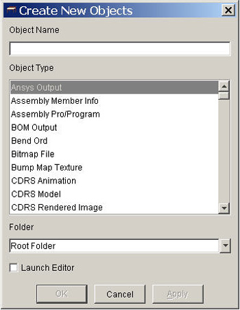
Customizing the Object New Menu in Pro/INTRALINK
Pro/INTRALINK has the capability to create new objects in your workspace. This
method involves using the selection Object >New from within the Workspace
browser. The problem is that to use this method, you must scroll through many
object types before coming across the Pro/ENGINEER object types. (See Figure
1.) This can be frustrating, but there is a way to solve the problem.
Figure 1
If you have administrator privileges within Pro/INTRALINK, you can send the
Pro/ENGINEER object types to the top of this list. Open the administration
portion of Pro/INTRALINK by selecting Administration from the main Pro/INTRALINK
menu or Intralink >Administration from within either the Commonspace or
Workspace browser. Once inside the administration portion of Pro/INTRALINK,
expand the Object category to view the available options. Select the Object
Types category to view all the defined object types in the database. The
system will sort according to the object type description field. To easily find
the Pro/ENGINEER object types, sort the Description column. Scroll to
find the descriptions that begin with Pro/ENGINEER.
There are a few ways to get the object types to appear at the top of the list.
Place a symbol or number in front of the description name. (See Figure 2.)
Figure 2
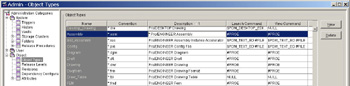
There are only a few Pro/ENGINEER types you need to put at the top of the
list. These are:
| Pro/ENGINEER Assembly |
| Pro/ENGINEER Drawing |
| Pro/ENGINEER Part |
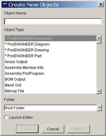
Using this technique, you can sort other object types commonly used within
your environment. To see what the Object New dialog looks like after the
change, select it from within the Workspace browser. The object types should
appear at the top of the list. (See Figure 3.)
Figure 3
--Submitted by Eric Horn, FroTime Inc., San Diego, CA
Creating a Four-Sided Box With Flanges on Top
This tip covers a fast way to create a standard four-sided box with flanges on
top. Typically, a Pro/E user would start the part in Pro/SHEETMETAL and create
each wall and flange separately. To save time, start the part in Pro/SOLIDS and
convert the part to Pro/SHEETMETAL. This cuts in half the amount of features it
takes to create the box or part. This is important when working with large
assemblies because it avoids lengthy regeneration times.
| Go to File >New Part >Subtype >Solid. |
| Create your solid protrusion with sharp corners. |
| Make a cut in the top of the box to create an opening. In making the cut
size, take into account the size of the flanges you require for the top of the
box. The depth of the cut would be blind. Set the depth to the thickness of
the material such as .125, .250 or .187. |
| Shell out the box by using Feature >Create >Shell. Select the
inside of the box as the material to remove. Select a thickness equal to the
number you selected for material thickness when you created your cut on the
top of the box. This guarantees uniform thickness. |
| Select Application >Sheetmetal and select a driving surface. Choose
the default thickness. The box is now a Pro/SHEETMETAL part. |
| Select Feature >Create Conversion. Select your point reliefs, edge
rip and rip connect. |
With this method, it takes only five features to create a four-sided box with
flanges on top.
--Submitted by Charles Niemotka, Tobyhanna Army Depot Pro User Group,
Tobyhanna Army Depot, Tobyhanna, PA
Automating Pro/E, Pro/INTRALINK Installation
Here is a not-so-well-documented technique that enables you to:
| Automate your Pro/E and Pro/INTRALINK installation. |
| Use PTC.Setup trail files. |
| Record every click and entry you make in the setup program and
automatically replay the steps for each new Pro/E installation. |
This will save a lot of time and prevent you from having to be at the
computer to make the right picks. Here are the details:
| Run your setup with the option -uilog on the command line: ptcsetup -uilog.
|
| Perform all the selections needed for a standard installation including
license servers, installation folder, etc. |
| The trail file ps_trl.txt.numeric suffix is created in the current folder.
Rename the trail file (for example, setup.txt) and place it in a convenient
place such as the bin folder. |
| Write a script to call setup within the trail file and place it in the
same folder: ptcsetup -uitrail setup.txt. |
There also is the option of running setup without displaying on screen (use -nographics
option): ptcsetup -nographics -uitrail setup.txt.
See the PTC description in TPI 103331 for more information.
This technique is especially useful for installing Pro/INTRALINK. You could
incorporate it into your standard installation procedure so all new clients are
set up with the correct paths, servers, etc.
--Submitted by Edwin Muirhead, CAD systems administrator, Aberdeen, Scotland,
UK and
www.geocities.com/proehelp/index.html?admin.htm#setup
Sizing Pro/INTRALINK Columns
To get your Pro/INTRALINK columns to be only as big as needed, point your mouse
over the column heading and hit the right-mouse button. They will adjust
automatically, usually narrowing to the longest entry listed.
--Submitted by Sandy Buerkle, designer, Welch Allyn Inc., Skaneateles Falls,
NY
Recreating Assemblies in Pro/MECHANISM Design
Although it is possible to convert existing assemblies into Pro/MECHANISM,
experience shows it is easier to recreate an assembly. One reason is that
components often are assembled in a different order than what is required within
Pro/MECHANISM.
Avoid conflicts between joint-axis settings and drivers. If joint-axis
settings and drivers conflict, the assembly may fail when running the motion. In
most cases, the failure is caused by the driving trying to push a component
beyond its joint-axis limits.
--Submitted by Ian Turner, design application support, CSC , MBDA UK Account,
Stevenage, UK
2003/04/28
Q1- Vol. III, Issue 16
Is there a way to cross-hatch (Xhatch) a section in which the hatching is
something other than lines? I would like to have circles or other shapes
repeated in my cross-hatching.
--Dan Bailey, product development engineer, Emerson Appliance Motors, St.
Louis, MO
A1.1- Vol. III, Issue 16
I can provide a partial answer to your question. To generate cross-hatching
other than the default "slanted lines", do the following in Pro/E 2000i^2:
| Pick Modify >Xhatching and select the cross-hatching you wish to
change. |
| In the MOD XHATCH menu, pick Retrieve. A selection of different
cross-hatch files (corresponding to different materials) will be available. In
the case of 2000i^2, the choices are rather limited (aluminum, copper,
electric, glass, iron, plastic, steel, titanium and zinc), and are just other
simple line patterns. These cross-sections are .xch files and are located in
the ":\ptc\Proe200i2\text\crosshatch" directory. |
The portion of your question left unanswered is where to find, or how to
generate other varieties of cross-hatch patterns to store in this or another
working directory. Perhaps others can answer this part or provide a better
solution.
--Richard Cruz, mechanical engineer, project engineering, Key Technology,
Inc., Walla Walla, WA
Q2- Vol. III, Issue 16
I just received Pro/E2001 and I am trying to create dimensions. It does not work
when I place my new dimensions in Sketcher or on the print itself. Is there a
special setting that I need to know about?
--Sue Coupal, drafter II, Eaton Corp., Selma, NC
A2.1- Vol. III, Issue 16
Your question is somewhat confusing. If you create a drawing and choose View
>Show and Erase, a window will open that gives you the option to pick
different types of dimensioning schemes. This function uses the dimensions that
you use in Sketcher when creating geometry.
--Garry Enyart, Fort Recovery Industries
2003/05/02
Q1- Vol. III, Issue 17
How do you organize Pro/ENGINEER files? In other words, which EDM/PDM system do
you use?
--Dirk Scherer, PROCAD GmbH & Co. KG , Projektleiter, Germany
A1.1- Vol. III, Issue 17
We use MatrixOne as our PDM solution. The MXPRO integration adds a pull-down
menu directly in Pro/E and is easy to use for file management and vaulting.
--Emmanuel Stathopoulos, senior mechanical engineer, Hyperchip Inc.
A1.2- Vol. III, Issue 17
We use Product Center from STI/WTC.
--Brian S. Lynn, CAD administrator/design drafter, Weil-McLain, Michigan
City, IN
Q1- Vol. III, Issue 16
Is there a way to cross-hatch (Xhatch) a section in which the hatching is
something other than lines? I would like to have circles or other shapes
repeated in my cross-hatching.
--Dan Bailey, product development engineer, Emerson Appliance Motors, St.
Louis, MO
A2- Vol. III, Issue 16
I do not know how to add circles as part of the pattern. You can however create
additional cross sections. Go to MOD XHATCH and retrieve one of the existing
patterns. You can add/delete lines as well as modify the font and weight. When
you finish, select Save, type the name of the pattern and hit Enter.
The pattern will be saved in your working directory. After saving it, you can
move it to the crosshatching directory. If you want to keep your custom patterns
separate from the defaults, create a new folder and add the following line to
your configuration file: pro_crosshatch_dir path. You can also assign crosshatch
patterns automatically to a cross section. In your part, assign a material by
selecting Set Up >Material >Define or Assign. (We utilize a
material library). Name your crosshatch files to correspond with the material
names. If the system finds a pattern with the same name as the material (without
the .xch extension), it automatically assigns it to the cross-hatch section.
--Randy Hagen, sustaining engineer, VIASYS Healthcare, Palm Springs, CA
2003/05/09
Q1- Vol. III, Issue 18
Can anyone explain to me why curves created between two points using the "thru
points" option are not accepted as trajectory during sweep feature creation? How
can I get around this?
--Manohar Dapakara, Eicher Motors Ltd., Indore, India
A1.1- Vol. III, Issue 18
These curves will be accepted if you use the single-radius or multiple-radius
options. Splines, which are the default curve types for thru points, cannot be
used as trajectories for a sweep.
--Thomas G. S. Peterek, Active Design Consulting Inc., Kitchener, Ontario,
Canada
A1.2- Vol. III, Issue 18
Assuming you are using Wildfire, use the variable section sweep.
--Niloy Guha, product executive-mechanical design automation, Rolta India
Ltd., Calcutta
A1.3- Vol. III, Issue 18
You can overcome this problem by using variable section sweep or swept blend.
--Ravi Kiran, application engineer, CSM Software Ltd., Banglore
A1.4- Vol. III, Issue 18
When curves between two points are created, often the end points of those curves
are unable to be perpendicular to the curve trajectory. There are two ways to
overcome this problem. After selecting the curve use the trim/extend command and
extend the endpoints for a specified distance. This allows for endpoint
alignment to a sketch plane because the extension is straight. The drawback to
this method is that only a single loop can be used for the sweep.
A second method is creating either a 2projection curve for complex
three-dimensional trajectories or a sketched curves. In Sketcher, select the
points you would like to go through as you sketch references for placement. You
will need a straight section for your start point, so the sketch plane can be
created perpendicular to the trajectory. These two-curve creation methods are
more powerful in that they will accept multiple-loop sketches and are less
likely to fail.
--Lee Hughes, Pro/E designer II, Kohler Co.
A1.5- Vol. III, Issue 18
When you create datum curve thru points and use them for sweep, Pro/E is not
able to find adjacent reference surfaces to determine the surface to which your
section will be normal. Use advanced option, selecting Feature >Create
>Protrusion >Advanced >Swept Blend. After selecting the datum curve as the
trajectory, Pro/E will ask you for a surface to which your section will be
normal. Show it that surface and you will accomplish your task.
--Yogesh Gaikwad, executive-product design and engineering, Fleetguard
Filters Pvt Ltd., Pune
A1.6- Vol. III, Issue 18
The reason you could not select the two-points curve as your sweep trajectory is
that you did not sufficiently define the orientation of the curve. Go back and
redefine the former two-points curve with its orientations and you will be able
to create your sweep with a two-points curve.
--Yang Xue Liang, senior project engineer, Xuzhou Meritor Axle Co. Ltd.
Q2- Vol. III, Issue 18
How can I set the attribute Name as the default instead of Branch
in the Locate Common Space Objects window of Pro/INTRALINK? I am using version
3.0 of Pro/INTERLINK.
--Sameeulla Baig, designer, Zamil Aircon, Dammam, Saudi Arabia
A2.1- Vol. III, Issue 18
Usually your administrator is the only one who can set this option but if you
have administrative rights, here is what you would do. Select Intralink
from the pull-down menu and click on Administration. Select Object
>Attributes >Object Attributes. Create an attribute called "Name" if there
is not already an attribute with that name. Select the pull-down menu and click
on Name and enter the value.
--Jeff Macon, engineering team member, eServ LLC, Rock Island, IL
A2.2- Vol. III, Issue 18
Set up your own locate folder. Here is how to set your computer to locate the
latest revision: (clock symbol) & version (clock symbol) along with the name
(=). To set up your own locate menu, pick Name (=) and select the
plus button on right. This should put it under Attribute >Operator.
Select Create and name your setup for Locate. Pick this file,
double-click in the value column and proceed as normal.
--Denise Hartranft, designer, Auburn Clutch Division
New Answers to Previous Questions
Q1- Vol. III, Issue 17
How do you organize Pro/ENGINEER files? In other words, which EDM/PDM system do
you use?
--Dirk Scherer, PROCAD GmbH & Co. KG , Projektleiter, Germany
A1.1- Vol. III, Issue 17
I use PTC's Pro/INTRALINK.
--Andy Singletary, engineering systems technology manager, Bristol
Compressors, Inc., VA
A1.2- Vol. III, Issue 17
We use the Windows NT Server, letting it handle security and permissions. This
is accomplished by creating subfolders. One folder is for users to work within,
one folder is for the Library data, one folder is for Pro/E and company
standards, one folder is for the release process and one folder is for the
released "golden" file. Everyone has read privileges to these folders, but
depending on their role in the engineering department, users may or may not
determine the folders to which they can write. To protect the files, we move
them from folder to folder. In Windows NT, we have to copy the files from folder
to folder and delete files to allow the file to gain the security permissions of
the folder. We have written programs using Excel and Visual Basic to assist in
moving files from folder to folder. The system works well, especially if you
have no money for PDM. It also mimics the way Pro/INTRALINK works to a certain
extent. Users have a workspace, the golden file folder is like common space and
the release process folder is similar to the promotion scheme. One problem is
the quality of the data. So to ensure data quality, we maintain the history of
prior released data in a Zip file. By renaming the Pro/E number on the end of
the file, we ensure that data is not lost. Another problem is duplicate data.
This system lends itself to using the backup-file command in Pro/E, so most of
our user directories are mini libraries. It has taken about a year to work out
the bugs and get everyone on board. We are trying to implement Pro/INTRALINK 3.2
at this time with the main goal being electronic signature. So far we have the
database running and configured and are beginning to import data.
--Doug Meyhoefer, principle mechanical engineer, L-3 Communications Display
Systems, Alpharetta, GA
A1.3- Vol. III, Issue 17
We use MatrixOne as our PDM solution. The MXPRO integration adds a pull-down
menu directly in Pro/E and is easy to use for file management and vaulting.
--Emmanuel Stathopoulos, senior mechanical engineer, Hyperchip Inc.,
Montreal, Canada
Q2- Vol. III, Issue 16
I just received ProE2001 and I am trying to create dimensions. It does not work
when I place my new dimensions in Sketcher or on the print itself. Is there a
special setting that I need to know about?
--Sue Coupal, drafter II, Eaton Corp., Selma, NC
A2- Vol. III, Issue 16
Select Insert >Dimension > New References and make your choice. There are
no sketched dimensions.
--Alejandro Arzate Silva, mold design engineer, Applica Manufacturing,
Querétaro, México
2003/05/15
View Manager in Pro/E Wildfire
The new release of Pro/E Wildfire has introduced many new user interface (UI)
components and as a result has shifted some commonly used functions. One of the
new UI components is the View Manager, which brings together previously separate
components into a single dialog box. The components that were in version 2001 of
Pro/E included:
| Simplified representations |
| Explode states |
| Model orientation |
| Component display |
(See Figure 1.)
Figure 1
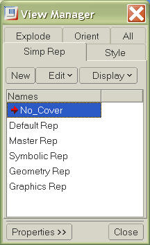
With the new View Manager, some of these components have new names.
Simplified Reps is Simp Rep. Model orientation is Orient. Explode
states is Explode, and Component display is called Style. The
names have changed, but the same functionality remains within the View Manager.
The way to get to these components, however, has changed.
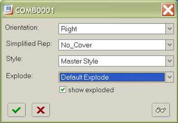
To learn the changes, experiment with the available options. One of the most
confusing is creating and defining a new simplified rep, explode, orient or
style. To do this, choose the New option and give it a new name. While it
is still highlighted, select the Edit >Redefine option. This will allow
you to define the new view state. When you create a new view state, Pro/E will
not have you define that state automatically. You must redefine it.
The View Manager allows you to define view states that include all four view
components. You can select from each of the following: Orientation, Simplified
Rep, Style and Explode. You also can choose either to explode or not explode the
view by using a check box. The check box is available because there is no
"unexploded" option in the pull-down menu. (See Figure 2.)
Figure 2
--Submitted by Eric Horn, vice president of research and development,
FroTime Inc., San Diego, CA
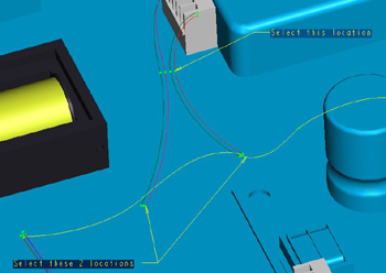
Creating a T Junction in Pro/CABLING
This technique will show how to create bundles using Pro/CABLING that form a
T-shaped junction. Consider the situation shown in Figure 1, where wires
form a three-sided branch.
Figure 1
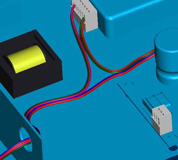
In Release 2001 and later, "branch" bundles can be created to represent
T-junctions of wires and cables.
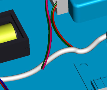
Select Feature >Create >Bundle, and enter a name for the bundle.
Select the type of grouping and whether or not it has a sheath. Use Along
Path and select the beginning and end locations of the horizontal segment of
the "T." Pro/ENGINEER will prompt, "Do you want to include partially routed
cables on the path?" Select Yes and use Sel All and Done Sel
to select all the wires to include in the bundle. Accept the default parameters
or enter new ones. A bundle will be created that encompasses the wires that run
along the horizontal portion of the "T." Figure 2 shows the result.
Figure 2
To create the vertical section of the junction, create another bundle and
select Branch from the BUNDLE OPTS menu. Pro/ENGINEER will prompt,
"Select one or two locations on a top loom bundle to define one end of the
branch." Select the two locations on the horizontal bundle where the wires of
the vertical portion of the "T" intersect it, and choose Done Sel.
Pro/ENGINEER will prompt, "Select a location to define the other end of the
branch." Select the location on the vertical wires where the bundle will begin.
(See Figure 3.)
Figure 3
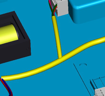
Pro/ENGINEER will create the second bundle. When finished, the bundles will
intersect in a T-shaped junction. (See Figure 4.)
Figure 4
--Submitted by Florin Neamtu, principal engineer, PTC technical support,
Needham, MA
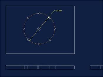
How to Show Bolt Circle Diameter on a Drawing
Frequently designers need to show the diameter of a circular bolt hole pattern
on a drawing. Doing this is much simpler than one would expect.
An option exists in the drawing.dtl file that is turned off by default. To
show the bolt circle diameter or radius (whichever you used for the pattern), go
to the Menu Manager and choose Advanced >Drawing Setup in 2001 or File
>Properties >Drawing Options in Wildfire.
From within the Drawing dialog box locate "radial_pattern_axis_circle," and
set the value to Yes. Choose View >Show and Erase from the
pull-down menus and show axis on the view to which you wish to display the bolt
hole circle. (See Figure 1.)
Figure 1
--Submitted by Thomas G. S. Peterek, Active Design Consulting Inc.,
Kitchener, Ontario, Canada. With thanks to Andrew Burke and Gabriel Martinez.
Showing Various Mechanism Positions Without MDX
In the "Drag Dialog", snapshot the mechanism position, use the "Make Available
in Drawing" icon to make the snapshot visible in the drawing. Set and snapshot
the mechanism at all the positions you wish to communicate. Make all available
to the drawing. A user without Mechanism Design can view the various mechanism
states by using the Explode State menu, with the use set at current to pick one
of the mechanism snapshots.
--Submitted by Ian Turner, design application support, CSC, MBDA UK Account,
Stevenage, UK
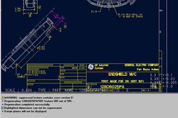
Ref. Dimensions in Drawing Mode
Sometimes users receive an error message saying, "Highlighted dimensions cannot
be regenerated." (See Figure 1.) When a Reference Dimension misses its
reference edge for regeneration of the created dimension, it can become
unattached. Delete the Ref. Dim. and create a new one. But you also can Reroute
Attached Edge by selecting the Ref. Dim and using the third-mouse button. Hold
it and select Reroute Attach and choose the new references.
Figure 1
--Submitted by Palle Srinivasa Reddy, senior engineer—CAD, GE India Business
Centre, Begunpet, Hyderabad, India
2003/05/16
Q1- Vol. III, Issue 19
In Pro/E 2000i, what is the best software to create graphical presentations
using my Pro/E models? I am finding that models pixilate heavily when I export
images as .tif files and open them in PhotoShop. Does 3D Studio or another
software prevent this distortion?
--Jamal Shoukry, design engineer, Opus Fena, Buckinghamshire, UK
A1.1- Vol. III, Issue 19
I have found that the best way to export models for presentation is by using
capture software such as Capture EZE Pro by Application Techniques, Inc. You can
capture the whole screen, just the model window or a part of the window and
export to a long list of file types. I prefer .jpg files.
--Frank Johns, design engineer, Newville, PA
A1.2- Vol. III, Issue 19
I've gotten better results using a screen-capture program such as Screenprint
than I have by directly exporting images. You can save the images in a variety
of file formats including .gif and .jpg.
--Keith Hooks, mechanical engineer, HHP
A1.3- Vol. III, Issue 19
Try rendering the output file as Postscript rather than .jpg or .tif. By doing
this, you can control the image size and DPI. I used this method to generate
images for a large trade show display and the results were excellent. For those
who do not have Photoshop, the output can be viewed using GhostView. GhostView
can be downloaded for free. Visit
ftp://mirror.cs.wisc.edu/pub/mirrors/ghost/gnu/ghostview/.
--Brett Burdick, manager of product development, Fi-Shock, Inc., Knoxville,
TN
A1.4- Vol. III, Issue 19
Making a .tif file requires time for menu selection, size choices, dpi (100-600)
and image depth (8-bit index, 24-bit RGB, mono, grayscale). Also .tif files are
huge. Instead, I use the Print Screen key function, which creates an image
instantly. I paste it into documents (Word, Excel, PowerPoint) and crop it. My
screen area is 1,600 x 1,200 pixels and this setting creates fine screen dumps.
To create engineering documents (i.e., GD&T on ECN), I use SnagIt5, which can
be found at www.techsmith.com.
A windows screen capture utility offers the option of what box zone on the
screen to capture; therefore, no cropping is required. You can paste different
areas in forms without having to save extra files, or you can save a file in one
of the seven file-type options. I open CompuPic from
www.photodex.com, paste,
"print screen" capture, adjust the image and save as one of the 12 file options
for future use in graphic suites—.bmp or .psd or .jpg.
--Carrie Ellen Hall, mechanical designer III, Thetford Corp., Ann Arbor, MI
A1.5- Vol. III, Issue 19
The easiest way to render models from Pro/E is to translate them into .iges or .vrml
formats, open them into 3dsmax and then render them. See images below.
Image 1
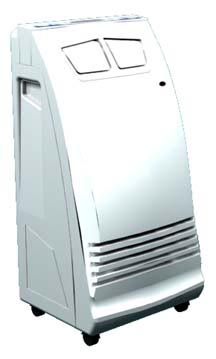
Image 2
--Chad Waldo, design engineer, R&D Tool and Engineering, Lees Summit, MO
A1.6- Vol. III, Issue 19
Increase the dpi of the output, but remember that doing this makes the file size
larger.
--Warren Weber, engineering manager, Bucher Aerospace Corp., Everett, WA
A1.7- Vol. III, Issue 19
I typically use Snagit to get pictures of Pro/E files. The picture will be
exactly what you see on the screen and you can save it in a number of formats.
You probably can download a test version from
www.techsmith.com.
--Claes Albertson, team leader mechanical CAD, Tetra Pak Carton Ambient AB,
Lund, Sweden
A1.8- Vol. III, Issue 19
To overcome this problem, simply save (do not export) the Pro/E file as a .jpg.
Once you open the .jpg file in Photoshop, you will see it is crystal clear.
3dsmax does the job best, but results vary depending on your graphics card.
--Pratik Madhavji, CAD designer, product developer, London, UK
A1.9- Vol. III, Issue 19
We use MS PowerPoint for presentations. To keep it simple and looking good we
use screen capturing. We position the model to the desired orientation and then
select Alt/Print Screen. (It's an old Windows trick.) This takes a
snapshot of your active window. If you want the full screen, use
Ctrl/Print Screen. Just paste the image into PowerPoint or the presentation
program of your choice. Once the image is in PowerPoint, you can crop, move and
resize it. It looks good and does not become pixilated. If you need a .jpg or
tif file format, use Save As and select the image format.
--Chris Novrocki, mechanical engineer, Lockheed Martin, Naval Electronics &
Surveillance Systems, Archbald, PA
A1.10- Vol. III, Issue 19
When I export Pro/E models, I export them as .jpgs at 600 dpi. When I open the
image in Photoshop, I am able downsize the image without losing detail or
causing it to pixilate.
--Matthew Fink, tech manual design, Miller Industries Towing Equipment Inc.,
Ooltewah, TN
Q2- Vol. III, Issue 19
In Wildfire when I make a sketch, the interface slows or is slow. I have
a Pentium4, 560 RAM memory and NVIDIA 32MB card. My graphics are excellent when
I spin solid features. What is the optimal requirement for Windows PCs?
--Alejandro Arzate Silva, mold design engineer, Applica Manufacturing,
Querétaro, México
A2.1- Vol. III, Issue 19
We had the same problem running PIII 800 with 512MB of RAM and a 32MB video
card. We upgraded to the NVIDIA 750XGL (128MB) graphic cards. This seemed to
solve our problem. Another thing I did was clear the computer and reinstall
everything from scratch. This seemed to help as well. Whenever my computers
start acting up and running slow, a good "Format C:" always seems to help.
--Aron J. Oler, senior drafting technician, Belden Wire & Cable - Electronics
Division, Richmond, IN
A2.2- Vol. III, Issue 19
Here is the link to the PTC website that shows the minimum and optimal
requirements for Wildfire:
www.ptc.com/partners/hardware/current/proe.htm.
--Kyle Davidson, Racar International, Anderson, IN
A2.3- Vol. III, Issue 19
Although you have a 32MB graphics card, I have heard from a couple different
tech support people that Wildfire is a graphics hog. When you are in Sketcher
you are using your graphics memory the most. A smaller card like yours will slow
it down. I have an Elsa Synergy II 32 MB graphics card and it does the same
thing on all of our machines. I heard the recommendations to run Wildfire are:
| Pentium 4 2.0 GHz processor (minimum) |
| 1.0GB RAM |
| NVIDIA Quadro4 900XGL 128MB graphic card. (On the NVIDIA website it notes
that this is a PTC-certified graphics card.) |
I am waiting for two new machines that are a step up based on the above
recommendations. They have:
| Pentium 4 2.4 GHz processor (minimum) |
| 1.5GB of RAM |
| NVIDIA Quadro4 900XGL 128MB graphics card |
We will see how much it helps.
--Sam Osier - designer, VIASYS Health Care - Critical Care Division, Palm
Springs, CA
A2.4- Vol. III, Issue 19
Change your graphics card. I had the same setup at home and the same problem
happened to me. Upgrade to at least 64 and it will be OK. But for the best
performance get a high-end graphics card such as a Wildcat. The problem does not
surface in 3D mode because 3D representatives do not use as much memory as
sketches. In sketches, you need more video memory due to accuracy settings.
--Abdul Mukmin Bin Burhan Tajuddin, product development engineer, Siemens VDO
Automotive, Malaysia
Q3- Vol. III, Issue 19
Where can I find online tutorials about Pro/E v2001 or Wildfire? I am looking
for a complete course in .pdf or .html format. Is it available on CDs and where
can I find it?
--Ramanan Selvam, tool design, LuK India Ltd., Hosur, India
A3.1- Vol. III, Issue 19
For online tutorials regarding Pro/E Wildfire, visit these sites:
www.ptc.com/community/proewf/newtools/index.htm
www.ptc.com/community/proewf/newtools/tutorials.htm
www.ptc.com/community/proewf/newtools/personal_productivity.htm
Also, there are often online courses from technical education organizations such
as universities. They are a bit harder to find, but are often free.
--Steffen Förster, MCAD application specialist, PTC, ICenter, Central Europe
A3.2- Vol. III, Issue 19
A California company called Frotime has .pdf files and models that you can
download. Some are free. Visit
www.frotime.com/home.asp.
--James Foster, contract designer, Honeywell Aerospace, South Bend, IN
A3.3- Vol. III, Issue 19
CADTRAIN offers a complete e-Learning curriculum for both 2001 and Wildfire. The
CADTRAIN content is web-based, so you can access it from any browser or you can
receive it on CD.
--Dave Cohen, vice president, CADTRAIN, Irvine, CA,
www.cadtrain.com
A3.4- Vol. III, Issue 19
I've found a brief tutorial for Pro/E Wildfire on the PTC site at
www.ptc.com/community/proewf/newtools/tutorials/1/. It is a 21MB Zip file
containing an html tutorial showing how to begin using Pro/E Wildfire in the
shortest amount of time. The tutorial assumes you are familiar with Pro/E. If
you are looking for a complete Pro/E tutorial, visit
www1.coe.neu.edu/~zeid/mim3350(spring01)/index2001.html.
--Luca Armellin, mechanical engineer, technical department director, Metelli
SpA, Cologne BS, Italy
A3.5- Vol. III, Issue 19
I've had great luck using Google to search "Pro +tutorial". Here's one link I
found:
www.caddigest.com/subjects/pro_engineer/tutorials_proe.htm
--Kevin P. Alexande, enterprise CAD/PDM consultant, Intergraph Solutions
Group, Cincinnati, OH
New Answers to Previous Questions
Q1- Vol. III, Issue 18
Can anyone explain to me why curves created between two points using the "thru
points" option are not accepted as trajectory during sweep feature creation? How
can I get around this?
--Manohar Dapakara, Eicher Motors Ltd., Indore, India
A1.1- Vol. III, Issue 18
You will have to use the swept blend feature under the advanced protrusion
option if the two points are not in the same plane. This is true even though the
cross-section of the protrusion is constant.
--Kevin Sullivan, product engineer, Nice Ball Bearings, Kulpsville, PA
A1.2- Vol. III, Issue 18
If you want use the curves that were created between two points using the Thru
Points option, you must define the attributes of the curve.
--Grand Fan, mechanical engineer, Casio Electronics Design Center (G.Z.) Co.,
Ltd., China
Q2- Vol. III, Issue 18
How can I set the attribute Name as the default instead of Branch
in the Locate Common Space Objects window of Pro/INTRALINK? I am using version
3.0 of Pro/INTRALINK.
--Sameeulla Baig, designer, Zamil Aircon, Dammam, Saudi Arabia
A2- Vol. III, Issue 18
It appears that you cannot change the default attribute listed for the Locate
Commonspace Objects browser. The most you can hope for is to create a saved
search and use that every time.
--William Robinson, CAD administrator, Valleylab, Boulder, CO
Q1- Vol. III, Issue 17
How do you organize Pro/ENGINEER files? In other words, which EDM/PDM system do
you use?
--Dirk Scherer, PROCAD GmbH & Co. KG , Projektleiter, Germany
A1- Vol. III, Issue 17
We use Product Center by Workgroup Technology, Corp./Softech, Inc. We have been
using it since 1997. It works well. It is stable and well seasoned. We are using
it primarily for vaulting all CAD data. It does a good job of revision control
because it understands the parametric relationship of the Pro/E files. (We
attempted to use a directory structure for a while but that became cumbersome,
inefficient and hard to control.) We also use Product Center for AutoCAD and
CorelDraw files. It is also capable of BOM and workflow tasks. Unfortunately, we
have other systems in place for these tasks.
--Bill Pier, supervisor, drafting design, Weil-McLain, Michigan City, IN
Q2- Vol. III, Issue 16
I just received ProE2001 and I am trying to create dimensions. It does not work
when I place my new dimensions in Sketcher or on the print itself. Is there a
special setting that I need to know about?
--Sue Coupal, drafter II, Eaton Corp., Selma, NC
A2.1- Vol. III, Issue 16
I've run into this situation when setting up new workstations. Check your mouse
settings and set the properties on the middle button to Middle Button.
This will enable placing dimensions in Sketcher and drawing modes. If the middle
button is not set properly, dimensions cannot be created in Sketcher or Drawing
modes.
--Rich Miller, designer, Siemens Energy & Automation, Inc., Spring House, PA
A2.3- Vol. III, Issue 16
Your question is somewhat confusing, but if you create a drawing and then choose
View > Show > Erase, a window will open that gives you the option to pick
different types of dimensioning schemes. This function uses the dimensions that
you used in Sketcher when creating your geometry.
--Garry Enyart, designer/CNC programmer, Fort Recovery Industries, Inc., Fort
Recovery, OH
2003/05/24
Q1- Vol. III, Issue 20
I was disappointed to find nothing written about Standard Triangulation Language
(STL) files in the article "Interoperability Creates Capability" by Tom Kopinski,
which ran on Page 12 in the March/April issue of Pro/E: The Magazine. My
experience is that this is a neutral file format that never causes problems
because it is a simple mathematical representation of a model. The .stl file
format handles the geometry as a skin of mating triangles that are only
represented by three coordinates (x,y,z). This file format is useful with rapid
prototyping machines and high-speed milling machines. I can export this file
format from Pro/E, but I'd also like to produce cutter location files based on
my .stl model. I can import them into Pro/MANUFACTURING, but the possibilities
end there. I cannot place a coordinate system and I cannot select the surface.
How does Pro/E handle this problem? Did I do I something wrong or is it
impossible to do this? This is important because in the future I think tool and
die makers will want to work with the .stl format.
--Jef Verheyen, MCAD user and teacher, De Nayer Institute, School for
Engineers
To read the Pro/E: The Magazine article in full or receive other
valuable Pro/E information, subscribe to Pro/E: The Magazine at
www.proe.com/orderonline.htm.
A1- Vol. III, Issue 20
STL files work great for rapid prototyping when each layer is a few thousand
surfaces thick. Smooth curves are not really possible in the process, anyway.
The fundamental issue is that it forms curved surfaces with a plethora of
triangles. You cannot choose a surface because it is not one surface—it is up to
thousands of possible surfaces. A way to reach an approximation is to use more
triangles, which can increase file size dramatically. That is one area where an
IGES or STEP conversion is superior.
--Al Irion, mechanical engineer, Chipless Metals, Mequon, WI
Q2- Vol. III, Issue 20
How can I edit the default light? It is impossible to sketch a new feature in
shaded mode without hanging the light. Using a mapkey seems to be the only
workaround, but I would like to solve this problem once and for all by editing
the default light.
--Pascal Leroux, industrial design technologist, INO, Sainte-Foy, Quebec,
Canada
A2- Vol. III, Issue 20
You have to use a mapkey. There is no other workaround unless Wildfire has
something to offer that I do not know about.
--William Robinson, CAD AdminValleylab, Boulder, CO
Q3- Vol. III, Issue 20
Does PTC have a deep-draw, metal-stamping simulation module available for Pro/E
Wildfire?
--Ross H. Liberty, owner, Factory Pipe, Ukiah, CA
A3- Vol. III, Issue 20
They have a die module. I design dies. PTC came to our office to do a
demonstration. The module was nice for simple progressive and bending dies. If
you are looking for software that helps develop the blank size or helps to show
where the material could crack, look into second-party software. Check out a
company called Automated Analysis Corp.
--Jason Pavloff, design engineer, Cosmos Manufacturing, South Chicago
Heights, IL
New Answers to Previous Questions
Q1- Vol. III, Issue 19
In Pro/E 2000i, what is the best software to create graphical presentations
using my Pro/E models? I am finding that models pixilate heavily when I export
images as .tif files and open them in Photoshop. Does 3D Studio or another
software prevent this distortion?
--Jamal Shoukry, design engineer, Opus Fena, Buckinghamshire, UK
A1.1- Vol. III, Issue 19
Re-sampling by 200 percent in Photoshop can help overcome some edge pixilation (jaggies)
of a screengrab. TIFF exports from Pro/E offer a higher resolution than do
screengrabs. But by selecting Save As and choosing anything other than a
snapshot, you will lose customized lighting. We use Okino Nu-Graf software to
produce images of models. (See image below.) This process can interpret .slp
render files that are exported from Pro/E. It is good value as far as cost.
Finished presentations vary in quality. PowerPoint is popular and LView Pro has
a handy slideshow. 
--David Robinson, Partner, London Associates Product Design, Berkhamsted, UK
A1.2- Vol. III, Issue 19
Please take a look at my PowerPoint presentation by clicking
here.
--Mike McGuire, industrial design consultant and principal, Mike McGuire
Design, and instructor, Carleton University, Ottawa, Canada
Q2- Vol. III, Issue 19
In Wildfire when I make a sketch, the interface slows or is slow. I have
a Pentium4, 560 RAM memory and NVIDIA 32MB card. My graphics are excellent when
I spin solid features. What is the optimal requirement for Windows PCs?
--Alejandro Arzate Silva, mold design engineer, Applica Manufacturing,
Querétaro, México
A2- Vol. III, Issue 19
I had same problem. Try making a centerline at the beginning of your sketch
(anywhere), and you will find that the Sketcher runs faster. In the meantime, we
both will eagerly await new machines.
--Antonio Pacheco, superior mechanical engineer/engineering manager, DIMEF,
Spain
Q3- Vol. III, Issue 19
Where can I find online tutorials about Pro/E v2001 or Wildfire? I am looking
for a complete course in .pdf or .html format. Is it available on CDs and where
can I find it?
--Ramanan Selvam, tool design, LuK India Ltd., Hosur, India
A3- Vol. III, Issue 19
Frotime has excellent tutorials that you can download from
www.frotime.com. They are
well made and very reasonably priced. They cover many subjects from detailing to
advanced surfacing.
--Steve Meek, KDM Design & Engineering, Inc., Grand Rapids, MI
2003/06/02
Q1- Vol. III, Issue 21
I would like to set the default shading quality to 10 using config.pro. Is this
possible, or do I have to reset it every time I launch Pro/E?
--Marty Ball, manufacturing engineer, Hersey Meters, Cleveland, NC
A1- Vol. III, Issue 21
The answer is in the Level of Detail config.pro options. Add these lines to your
config:
lods_enabled YES
lods_value 100
lods_enabled
yes, no
These will determine whether or not the system uses Level of Detail in shaded
models during dynamic orientation (panning, zooming and spinning).
When you type "yes", the Level of Detail is enabled. With "no", the Level of
Detail is not enabled. You can override this option's setting at run time by
selecting Levels of Detail in the Environment dialog box available from the
Utilities menu. If Levels of Detail is enabled, the value (lods_value) specifies
the default value used to display lods. The value is a percentage of the edge
size vs. the total size of the model. Use "smooth_lods" and "yes, no" to work
with "lods_enabled" to smooth the levels of detail when a model is shaded. Note
that "smooth_lods" and "yes, no" is an optional setting.
--Chris Novrocki, mechanical engineer, Lockheed Martin, Naval Electronics &
Surveillance Systems, Archbald, PA
Q2- Vol. III, Issue 21
While using repeat regions for BOM, I want S.No column (& rpt.index) to start
with .001 instead of 1. How can I do this?
--Mohan Natarajan, TI consultant, GE India Business Centre, Hyderabad, India
A2- Vol. III, Issue 21
You may be able to accomplish this through repeat region relations. Try changing
the text when you switch symbols to something like: asm.mbr.custom_rpt_index. In
relations, set rpt.index=asm.mbr.custom_rpt_index and in the next line, multiply
asm.mbr.custom_rpt_index by .001. Add custom_rpt_index to your repeat region
parameters. I'm not sure if this will work, but it is how we modify entries in
repeat regions.
--Brian J. Hart, mechanical engineer, Pro/E administrator, Lockheed Martin
NE&SS-Archbald, Archbald, PA
Q3- Vol. III, Issue 21
Using Pro/E 2001,we want to export drawings into AutoCAD because many of our
customers still use it. When exporting from Pro/E, it changes the fonts and
scales and new dimension creation is not allowed in AutoCAD. How should we
handle this?
--Jigar Narendra Talati., director, Hexagon Design Center, India
A3.1- Vol. III, Issue 21
Before exporting to AutoCAD, control the font size and scale through a DTL file
in Pro/E. In drawing mode, select advance/draw setup/.
- Drawing units - mm/inch
- Drawing text - height
This is how we control font size and scale.
--D. Karthik, Nestech Consulting, Coimbatore, India
A3.2- Vol. III, Issue 21
Export the .drg into .dxf so that the text is intact. Open the .dxf file in
AutoCAD and save it as an AutoCAD .dwg file. Check out the config.pro options "dwg_export_format"
and "dxf_export_format". You should set this option to 14. By doing this, you
will be able to create new dims in AutoCAD.
--Yogesh Gaikwad, executive-product design and engineering, Fleetguard
Filters Pvt Ltd., Pune, India
A3.3- Vol. III, Issue 21
I can address the portion of the question pertaining to scale. Pro/E exports all
of the drawing entities in paper (draw) scale. It has the ability to create
to-scale geometry so long as the geometry is not in a scaled view. Here is an
example: Create a 10-inch cube and on the drawing set the drawing scale to 1:1.
Create a non-scaled view and a scaled view at half scale. Make sure you have
these configuration settings: dxf_out_scale_views yes and dxf_out_drawing_scale
yes. Export the drawing and open the .dxf in AutoCAD. Measure the length of one
of the edges of the cube in the non-scaled view. It should measure 10 inches.
Measure the same edge in the scaled view. It should measure 5 inches. See images
below.
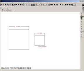
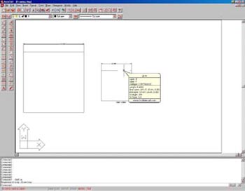
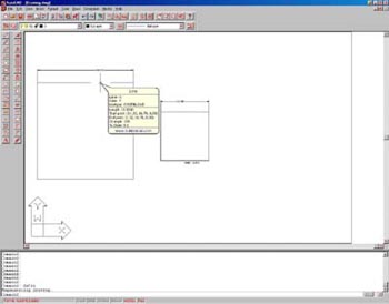
Here are some links to related articles from PTC's Knowledgebase:
www.ptc.com/cs/cs_23/faq/det2_faq.htm
www.ptc.com/cs/help/2001/html/usascii/proe/interfac/export_d.htm.
And this is what PTC engineers told me when I submitted a call on the view
scale factor: "After exporting either a .dxf or .dwg to AutoCAD, the file is not
usable by a AutoCAD user due to a view's scaling factor, applied to "Measurement
Scale - Scale Factor". Status details: The current functionality of Pro/ENGINEER
will not consider the scale of a view when it is opened in AutoCAD. The scale of
the drawing is used."
--Juan Rodriguez, York International Corp., York, PA
New Answers to Previous Questions
Q2- Vol. III, Issue 20
How can I edit the default light? It is impossible to sketch a new feature in
shaded mode without hanging the light. Using a mapkey seems to be the only
workaround, but I would like to solve this problem once and for all by editing
the default light.
--Pascal Leroux, industrial design technologist, INO, Sainte-Foy, Quebec,
Canada
A2- Vol. III, Issue 20
I also find it annoying to try and sketch with the default light setup. To
change the light select View > Model Setup >Lights. A new window will
open that allows you to add/delete different light types. You can change the
position, intensity and color of each light. Once you have the lighting set up
the way you want, save the settings by selecting File >Save. You can set
up and save several light files for different situations. To retrieve a light
file, select View >Model Setup >Lights >File >Open and go to where you
stored the saved light files. Select the file and select Open.
--Randy Hagen, VIASYS Healthcare, Palm Springs, CA
We are rerunning this answer with a correction supplied by the author.
Q1- Vol. III, Issue 20
I was disappointed to find nothing written about Standard Triangulation Language
(STL) files in the article "Interoperability Creates Capability" by Tom Kopinski,
which ran on Page 12 in the March/April issue of Pro/E: The Magazine. My
experience is that this is a neutral file format that never causes problems
because it is a simple mathematical representation of a model. The .stl file
format handles the geometry as a skin of mating triangles that are only
represented by three coordinates (x,y,z). This file format is useful with rapid
prototyping machines and high-speed milling machines. I can export this file
format from Pro/E, but I'd also like to produce cutter location files based on
my .stl model. I can import them into Pro/MANUFACTURING, but the possibilities
end there. I cannot place a coordinate system and I cannot select the surface.
How does Pro/E handle this problem? Did I do I something wrong or is it
impossible to do this? This is important because in the future I think tool and
die makers will want to work with the .stl format.
--Jef Verheyen, MCAD user and teacher, De Nayer Institute, School for
Engineers
A1- Vol. III, Issue 20
STL files work great for rapid prototyping when each layer is a few thousandths
of an inch thick. Smooth curves are not really possible in the process, anyway.
The fundamental issue is that it forms curved surfaces with a plethora of
triangles. You cannot choose a surface because it is not one surface—it is up to
thousands of possible surfaces. A way to reach an approximation is to use more
triangles, which can increase file size dramatically. That is one area where an
IGES or STEP conversion is superior.
--Al Irion, mechanical engineer, Chipless Metals, Mequon, WI
2003/06/06
Q1- Vol. III, Issue 22
Our organization has ANSYS and also Pro/MECHANICA. Can anyone offer us general
guidelines that indicate when is it best to use ANSYS for FEA and when we should
use FEA in Pro/E? Or at least can anyone lead us to documentation that compares
the FEA capabilities of the two?
--Rodzaki Mat Saad, Device Analysis Lab, Advanced Micro Devices, Penang,
Malaysia
A1.1- Vol. III, Issue 22
It depends on many factors including the goals and complexity of the project,
the details of results you would like to achieve and the designer's skills and
taste. ANSYS is powerful software for FEA and is capable of solving complicated
multi-physics problems. It is especially helpful when combining mechanical,
electrical, thermal and fluid features. Pro/MECHANICA is also good, but
sometimes limited because it is designed to solve mechanical problems. While the
simplest way to perform FEA is within Pro/E, the results are not detailed.
Designers should use Pro/E FEA to check their models. If you create simplified
models (in 2D or another elementary solid), ANSYS or Pro/MECHANICA modelers are
sufficient. For more complicated 3D work, generate the model in Pro/E, import
the model into ANSYS and use the FEA procedures. I am not familiar with any
references in the extensive FEA literature that compares these three software
products. I appreciate and use all of them. Sometimes only personal experience
will reveal the unique features of each.
--Zachary Popov, associate professor, department of heat technologies and
control, Technical University of Varna, Bulgaria
A1.2- Vol. III, Issue 22
Our organization also has ANSYS and Pro/MECHANICA. The biggest difference
between the two has to do with ANSYS' additional abilities to solve the most
complex structural problems. If we have a linear-stress problem, we will most
likely solve it in Pro/MECHANICA. If the problem has non-linearities, such as
stress-dependent properties, we will use ANSYS. Pro/MECHANICA has some
capability to solve non-linear problems, such as contact stress (which I really
like). But Pro/MECHANICA does not have the range of non-linear capabilities that
ANSYS has. If you have ANSYS Multiphysics, you also can solve fluid dynamics
problems and magnetic field problems. This can be important, for example, if you
are working in an area where you need more than an educated guess at the
convective heat-transfer coefficient.
--Dave Maxham, senior member of the technical staff, Tyco Telecommunications,
Eatontown, NJ
Q2- Vol. III, Issue 22
Can anyone tell me how to use the style feature or where to find examples that
show how to use this feature?
--Vighnesh D. Bhandari, project engineer, QuEST, Bangalore, India
A2.1- Vol. III, Issue 22
A style feature is created by using the interactive surface design extension. A
style feature is one feature that contains many pieces of geometry (curves,
surfaces and points). It is used to create stylish, curved surfaces.
--Jason Bailey, Sipco Molding Technologies, Meadville, PA
A2.2- Vol. III, Issue 22
Style is a feature provided by Pro/E for creating advanced curves and surfaces.
It allows you to create high-quality, freeform curves or directly create curves
on surfaces (instead of creating a curve on a plane and then projecting/forming
on a surface). Most of this information is available in PTC help.
--Deepak Bhat S., PLM Aerospace, Wipro Technologies, Madhapur, Hyderabad
Q3- Vol. III, Issue 22
How can I run design animation and capture it to a file without showing that it
has been made from a simplified representation? I am referring to that message
that is on the bottom right-hand side of the Pro/E window.
--Csaba Torok, product design engineer, C3D Ltd., Hungary
No answer yet. Do you know the answer? If so, please send it
here.
Please list the question you are answering and include your full name, title,
company name and address.
A3- Vol. III, Issue 21
I run into the same problem and I am always going from one to another. As for
entering your Pro/E drawing into AutoCAD, I create the Pro/E drawing as a block
so I can compare what I have unexploded and dimension it out of scale to the
Pro/E block drawing. There must be a better way.
--Michael Contreras, engineering tech III, AMSAFE Commercial Products,
Phoenix, AZ
Q1- Vol. III, Issue 17
How do you organize Pro/ENGINEER files? In other words, which EDM/PDM system do
you use?
--Dirk Scherer, PROCAD GmbH & Co. KG , Projektleiter, Germany
A1- Vol. III, Issue 17
We use MatrixOne as our PDM solution. The MXPRO integration adds a pull-down
menu directly in Pro/E and is easy to use for file management and vaulting.
--Emmanuel Stathopoulos, senior mechanical engineer, Hyperchip Inc.,
Montreal, Canada
2003/09/11
What's Up With Pro/INTRALINK 3.3?
Pro/INTRALINK 3.3 (released last month) is the first of PTC's data management
software tools that is fully compatible with objects created in Pro/E Wildfire.
(See Figure 1.)
Figure 1

Pro/INTRALINK 3.3 contains functionality allowing it to take advantage of
Wildfire's user interface. One of the most noticeable things is how Pro/INTRALINK
interfaces with Pro/E Wildfire. Instead of having a separate workspace or
commonspace window open to view Pro/INTRALINK objects or folders, the
information can be displayed in the Folder Navigator window inside Pro/E
Wildfire. (See Figure 2.)
Figure 2
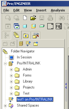
Workspace and commonspace folder contents are displayed in detail in the
Pro/E Wildfire browser window. (See Figure 3.)
Figure 3
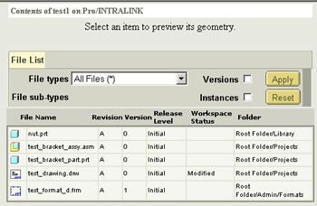
The folder navigator allows you to filter the type of files displayed in the
browser window and it gives you the ability to hide family table instances, as
well. Individual files can be selected and the object will be displayed in the
preview section of the browser window via ProductView Express.
To open files, drag them from the browser window directly into the graphics
window or simply double-click on them.
It is possible to check in modified objects directly from the Pro/E Wildfire
File pull-down menu (See Figure 4.) The Update command also is available
in this menu.
Figure 4
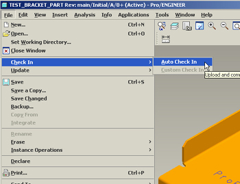
Another new functionality with Pro/INTRALINK 3.3 and Pro/E Wildfire is the
ability to switch workspaces without having to exit the session. When performing
this operation, the only requirement is that you erase all objects from the
session.
The way that Family Table objects are handled with Pro/INTRALINK 3.3 has been
vastly improved. It is possible to "designate" a file-based attribute of an
individual instance. These values can be modified in Pro/INTRALINK instead of
having to do the modification inside Pro/E. Also new for family table instances
is how the verification state of an object is communicated directly from Pro/E
Wildfire to Pro/INTRALINK. Pro/E Wildfire also saves all family table instances
to the workspace, even if they have not been verified. When a family table
instance is modified inside Pro/INTRALINK, its status is changed to "Not
Verified" to let the user know that verification has not taken place on the
modified instance.
Pro/INTRALINK 3.3 provides a Resolution Tool to check out versions of family
table objects different from those that exist in the active workspace. It is
possible to view the versions that are missing from or present in the version in
conflict, allowing users to correct the problem in Pro/E and complete the check
out.
Other Pro/INTRALINK 3.3 enhancements for family table objects include
improvements to the Duplication and Modification functionalities.
Pro/INTRALINK 3.3 has many improvements that allow it to interface with new
functionality in Pro/E Wildfire. It may not be long before Pro/INTRALINK and
Pro/E become a single software tool instead of two separate packages.
--Submitted by Stan Balish, president and chief executive officer, FroTime
Inc., San Diego, CA
Patterns and More Patterns
If you have a feature in which you want to use dependent copies in more than one
differing pattern, you normally have to make the dependent copies before you
pattern the parent. Otherwise, Pro/E will try to copy the pattern of the parent
as well.
There is a technique that allows you to make dependent or semi-dependent
copies after you have patterned the parent. The child pattern type can be fully
independent of the parent pattern type.
The trick comes when creating the dependent copy of the parent, selecting the
feature positioning dimensions and references and selecting the number of
occurrences, and setting that to 1, particularly if the parent is a
table-based pattern. The child pattern will be created with a single occurrence.
You can delete the child pattern (but not the child), which should leave you
free to create a new pattern of the dependant child in whichever way suits you.
Another useful technique is to select the same dimension for both the first
and second directions, which enables a double-stepped pattern. You also can turn
this pattern into a group and then step it (or double step it) in a different
direction, ending up with an overall pattern with up to four occurrence values.
Click here to view a PDF that shows two sheets of a quad-repeating pattern.
This is a double-stepped pattern in the x direction and double-stepped, group
pattern in the y direction. Only the initial bottom left square is a sketch. The
second sheet is a modification to show that even the first example can be
improved upon.
--Submitted by Patrick Morris, product designer/mechanical engineer, Allied
Telesyn Research, Christchurch, New Zealand
Pro/ENGINEER Wildfire, Drawing Mode
There is a hidden dialog box that automates the creation of drawing views. The
Drawing View menu manager does not display after this option is applied, and the
Insert Drawing View icon is no longer active. All views must be created using
Insert >Drawing View after the option is added.
Click: Tools >Options >type new option (it does not appear on the
Options list): Option: new_drawing_view_ui Value: Yes > Add/Change > Apply >
Close
Insert >Drawing View >General >pick a position for the view >the new
Drawing View dialog box opens
You can now select Categories: Type, Visibility, Section, Scale,
Representation, View Display, and Origin & Alignment.
View name, Type, and Presentation can also be determined with the new
dialog box.
--Submitted by Louis Gary Lamit, instructor, De Anza College, Cupertino, CA.
Author-Pro/ENGINEER Wildfire, Brooks Cole Publishing
Speeding Regeneration When Creating Family Tables
When creating family tables, create all the static features and then create the
variable features at the end of the model tree. This will speed regeneration
because Pro/ENGINEER will regenerate the model from the first variable feature
onward. In a model with 20 features, where 10 features are variable, the best
result is that 10 features will regenerate where the static features are located
before the variable features in the model tree. However if the first feature is
variable, then 20 features will regenerate.
--Submitted by Ian Turner, design application support and chairman Pro/UK
User Group, CSC, MBDA UK Account, Stevenage, UK
Function Name Changes in Wildfire
I recently installed Pro/ENGINGEER Wildfire and have found the following command
name changes:
| Previous Versions |
Wildfire |
| Modify |
Edit |
| Redefine |
Edit, Definition |
| Reroute |
Edit, Reference |
--Submitted by Karen Thacker, design engineer, Physitron Inc., Huntsville, AL
2003/06/13
Q1- Vol. III, Issue 23
I changed the config.pro with the parameters pro_unit_length and pro_unit_sys to
millimeters (mm.n.s). But whenever I create a new part or assembly, the system
of units in the Units Manager reverts to inch.lbm.sec. How can I configure Pro/E
to create parts and assemblies in mm.n.s without changing the system of units in
the Units Manager?
--Alejandro Arzate, mold design engineer, Applica Manufacturing, Queretaro
Mexico
A1.1- Vol. III, Issue 23
Pro/E has default templates to start parts, assemblies and drawings. The system
uses the inch files by default. If you set a config option template_designasm
and template_solidpart to point to the metric parts, all new parts and
assemblies will start as metric. There are more templates than just these two.
Open the Options dialog box (located under Tools >Options) and type the
word template in the Option box at the bottom left-hand side of the box. Click
Search and you will see a list of all the templates available. These
reside in a directory called "templates" located in the loadpoint directory for
Pro/E. The templates can be modified and stored back to this directory or you
can create a new set and use the config.pro file to point to the new directory.
--Tom Peterek, Active Design Consulting Inc., Ontario, Canada
A1.2- Vol. III, Issue 23
One way to get around this is to create a Start Part or Assembly. In your Start
Part or Assembly, set your units to mm.n.s. You can set up this part any way you
like to include special layers, relations, material, parameters, etc. Every time
you create a new part or assembly, click (in Version 2001) New >Part.
Name your part, uncheck the use-default template and click on Browse.
Select your Start Part or Assembly. Your new part or assembly will have all the
settings (units, etc.).
--Jeff Macon, engineering team member, eServ LLC, Rock Island, IL
A1.3- Vol. III, Issue 23
You should use a template with the units you want. If you want to use this one
as the default template add the template_solidpart option to the config.pro with
the path of the file you have created for solid parts. For assemblies, use
template_designasm.
--William Quintero, mechanical designer, PROTRAFO Cax, Bogotá, Colombia
A1.4- Vol. III, Issue 23
If you are creating new parts from a start part, check the units. Start parts
created before you changed the config.pro parameters will retain the old system
of units.
--Bob Fresco, engineering services manager, Honeywell Sensotec, Columbus, OH
A1.5- Vol. III, Issue 23
The system of units depends on which template you are using while creating a new
part. If you a have predefined template in which the units are set to mm.n.s,
your part will adopt those units. Also take note of the directory where it is
storing the config.pro. It should be in same directory in which you are starting
Pro/E. In other words, it should load that config.pro to where you have
configured the options.
--Yogesh Gaikwad, executive-product design and engineering, Fleetguard
Filters Pvt Ltd., Pune, India
A1.6- Vol. III, Issue 23
It depends on which version of Pro/E you are using. In Pro/E 2001, select
Utilities >Options. Search for the option template_designasm. Browse
and select the file < loadpoint >\templates\mmns_asm_design.asm. Do the
same for the rest of the template_options:
template_solidpart < loadpoint >\templates\mmns_part_solid.prt
template_mold_layout < loadpoint >\templates\mmns_mold_lay.asm
template_mfgmold < loadpoint >templates\mmns_mfg_mold.mfg
template_mfgcast < loadpoint >\templates\mmns_mfg_cast.mfg
template_sheetmetalpart < loadpoint >\templates\mmns_part_sheetmetal.prt
Template parts, template assemblies and template mfg models are empty files that
may contain datum features such as planes, CSs, points, curves and parameters.
Define the units that you want to create or create a new system of units.
--Kaminakis Nikos, applications engineer, INFOCAD S.A., Maroussi, Athens,
Greece
Similar answers were provided by George Mantzaflaras, applications
engineer, Infocad S.A, Athens, Greece; Sameeulla Baig, designer, Zamil Air
Conditioning, Dammam, Saudi Arabia, and Kurt Stark, Alphasem AG, Berg,
Switzerland.
New Answers to Previous Questions
Q2- Vol. III, Issue 22
Can anyone tell me how to use the style feature or where to find examples that
show how to use this feature?
--Vighnesh D Bhandari, project engineer, QuEST, Bangalore, India
A2- Vol. III, Issue 22
Refer to "Pro/ENGINEER Wildfire for Engineers & Designers" by Sham Tickoo
published by Dreamtech Press. This book covers the style environment of Pro/E
Wildfire. Tutorials and examples are given that help users apply the style tools
while solving standard problems. All the tools available in the style
environment are discussed in Chapter 13 with examples. The book will be
available June 15 and can be ordered via
www.cadcim.com. The book is
also available in bookstores in India.
--Abhinav Rai, co-author of "Pro/ENGINEER Wildfire for Engineers &
Designers", Dreamtech Press
Q3- Vol. III, Issue 22
How can I run design animation and capture it to a file without showing that it
has been made from a simplified representation? I am referring to that message
that is on the bottom right-hand side of the Pro/E window.
--Csaba Torok, product design engineer, C3D Ltd., Hungary
A3- Vol. III, Issue 22
The only way I know is to render the animation output. Depending on the length
of the animation, this may take a lot of time. You will not see the simplified
representation in the animation.
--Dave Simpson, mechanical engineer, Loudspeaker Research & Development, QSC
Audio Products, Inc., Costa Mesa, CA
2003/06/23
1- Vol. III, Issue 24
Are there viewers available for download that make it possible to open and view
various designs in Pro/E, SolidWorks, Solid Edge, Inventor and Unigraphics?
--Lee Test, production control manager, The Gem City Engineering Co., Dayton,
OH
A1.1- Vol. III, Issue 24
I would recommend AutoVUE from Cimmetry. It's not free, but it's inexpensive
given the capabilities it offers.
--Ted Smith, account manager, National Technical Support Center, IMAGINiT
Technologies, Mississauga, Ontario, Canada
A1.2- Vol. III, Issue 24
Take a look at
www.virtuale3d.com/vcollab.asp for information about VCollab. VCollab can be
used to import the files from Pro/E, SolidWorks, SolidEdge, Inventor,
Unigraphics, ODEAS, CATIA V4, CATIA V5, ANSYS and NASTRAN for high-end
visualization. VCollab helps users load large CAD files almost 50 to 75 times
faster than most programs and allows users to interact with large data on simple
Windows platforms at good frame rates. It also can cut dynamic sections,
generate stereo images, measure and mark up data and collaborate visually with
remote teams.
--Prasad Mandava, VirtualE3D USA Inc., Richardson, TX
A1.3- Vol. III, Issue 24
Our company has a viewer for STEP files. Most (if not all) CAD systems have STEP
export capability. See
www.steptools.com/products/stviewer/ for more details.
--Alexey Lipatov, STEP Tools, Inc., Troy, NY
A1.4- Vol. III, Issue 24
Spinfire from Actify will open most file formats. It is not free, but there is a
trial with a limit on the number of conversions you can do. Have a look at
www.actify.com/v2/solutions/index.htm.
--Sam Worthington, Manchester Science Enterprise Centre, England
Q2- Vol. III, Issue 24
Why does the name on the default home page of the Wildfire browser keep changing
(i.e., Hello Dave; Hello Janet, Hello Sanjay)? Sometimes it changes to names of
people who do not even work for our company.
--Dave Simpson, mechanical engineer, Loudspeaker Research & Development, QSC
Audio Products, Inc., Costa Mesa, CA
No answer yet. Do you know the answer? If so, please send it
here.
Please list the question you are answering and include your full name, title,
company name and address.
Q3- Vol. III, Issue 24
My current project is to identify the development of CAD/CAM in the furniture
industry. Do you have any suggestions as to where I might find information
regarding this topic?
--Rob Mahurin, student, Mississippi State University, School of Architecture,
Graduate Studies Program, Digital Research and Imaging Lab, Mississippi State,
MS
A3.1- Vol. III, Issue 24
Steelcase, Haworth and Herman Miller are the largest office furniture
manufacturers in Michigan. Steelcase uses Pro/E and has built a great deal of
CAD/CAM/CAE technology around the software. I don't have any direct contacts but
I'm sure if you visit their websites you could track down someone to talk to.
Also, the SMUG (Pro/E Southwest Michigan User Group) has a website and some of
its members are from these companies.
--Britt Mott, design engineer, Eaton Corporation, Marshall, MI
A3.2- Vol. III, Issue 24
Check to see if you can contact someone from the engineering department at
Flexsteel. At one time they had a company in Dubuque, IA.
--Michael Colson, sales engineer, Northstar Power Co., Ankeny, IA
New Answers to Previous Questions
Q1- Vol. III, Issue 23
I changed the config.pro with the parameters pro_unit_length and
pro_unit_sys to millimeters (mmns). But whenever I create a new part or
assembly, the system of units in the Units Manager reverts to inch.lbm.sec. How
can I configure Pro/E to create parts and assemblies in mm.n.s without changing
the system of units in the Units Manager?
--Alejandro Arzate, mold design engineer, Applica Manufacturing, Queretaro
Mexico
A1.1- Vol. III, Issue 23
Start parts and start asms contain the units.
--Duane Poe, drafting and design team leader, Leoni Wiring Systems, Inc.,
Design Center, Columbus, IN
A1.2- Vol. III, Issue 23
Configure your start part(s) and assembly(ies) to the desired configuration.
This should give you the results you are looking for.
--Krystal Streib, CAD administrator, MetalTek International, Carondelet
Division, Pevely, MO
A1.3- Vol. III, Issue 23
Go to Pro/E dir/templates and rename all inlbs_* files name to mmns_* and
reverse.
--Miodrag Bojovic, Mold Designer, Metalka, Serbia and Montenegro
A1.4- Vol. III, Issue 23
To set up units to default to millimeters you have to start earlier from where
you are beginning the part. Look at the input box for creating a new part. Does
it have a check mark by 'Use default template'? If it does, uncheck it. This
will give you a list of the templates that are available for use as start parts.
For part creation, there should be four available - an inch and metric solid
part template and an inch and metric sheet metal template. The default one is
already highlighted for selection. If it is the inch solid part, there are
parameters you will have to change in the config.pro to set millimeter part as
the default.
In config.pro, there are a series of parameters beginning with
template_designasm and ending with template_solidpart. To be
consistently metric, each of these values should be set to the metric start
part. For example, template_solidpart should contain the value
mmns_part_solid.prt. These are the actual names of Pro/E part, assembly,
manufacturing or mold files found in the default installation at [loadpoint]/TEMPLATES.
All the millimeter file names need to be added or changed for the
template_options.
The only complication to this is if the system administrator created a new
start part directory with company-created and regulated start parts in it. The
config options identify it is start_template_dir. If this option exists
in the config.pro (or config.sup) file, you are probably not using the files
from the default installation. You will have to look in that directory for the
metric template files for parts and assemblies. The names of the metric template
files will have to be assigned to template_designasm, etc. The values you
now have for pro_unit_length probably are being overwritten by an inch
start part. To check, find and open a millimeter part template file. Then go to
setup/units. The units should be set to metric correctly.
--David Janes, designer, San Diego, CA
Q2- Vol. III, Issue 23
How do you make a model of a conical compression spring?
--Phillip Fortney, mechanical engineer, LSA Communications, Exton, PA
A2- Vol. III, Issue 23
To model a spring, go to advance feature, then helical sweep. If you want a
conical or funny shape, just give it a different profile.
--Min Jin, mechanical designer, Arpeco Engineering Ltd., Mississauga,
Ontario, Canada
Q2- Vol. III, Issue 22
Can anyone tell me how to use the style feature or where to find examples that
show how to use this feature?
--Vighnesh D Bhandari, project engineer, QuEST, Bangalore, India
A2- Vol. III, Issue 22
Try this web link on PTC's site:
www.ptc.com/products/proe/isdx/efs4763/efs4763.htm.
--David Janes, designer, San Diego, CA
2003/06/27
Q1- Vol. III, Issue 24
Are there viewers available for download that make it possible to open and view
various designs in Pro/E, SolidWorks, Solid Edge, Inventor and Unigraphics?
--Lee Test, production control manager, The Gem City Engineering Co., Dayton,
OH
A1.1- Vol. III, Issue 24
Attached is a JPG of the interface of a viewer program called 3d-tool, which is
a fantastic viewer and by far the best I have ever used. What is even better is
the price of approximately $200 Australian ($100 US). It runs as a
self-contained program (EXE) so the receiver does not need to have a copy of
3d-tool to run the viewer. Just double-click on the EXE file. It supports IGS,
STEP, STL, SLP, XGL, 3DS, OBJ, DXF and ASC. I know it works with Pro/E (SLP) and
SolidWorks (STL). You can add notes to your parts, colors, transparency, basic
animation, etc. The company's website is
www.3d-tool.de. To use the
tool:
| Use the left-mouse button to rotate. |
| Hit ctrl and the left-mouse button to zoom. |
| Use the left-mouse button to pan. |
--Michael Cornish, product engineering designer, Cobalt | Niche Design,
Victoria, Australia
A1.2- Vol. III, Issue 24
Pro/E has a free desktop to design parts and can open PRT and ASM files. It also
has another product that will let you open DRW files. Check PTC's website for
free downloads.
--Warren Weber, engineering manager, Bucher Aerospace Corp., Everett, WA
A1.3- Vol. III, Issue 24
Use Delcam's PS-Exchange to view files after downloading and installing. The
viewer is free. The actual use of the program is a converter that is expensive
to use. It cost $55 for each use.
--John Irvin, president, Neco Inc., Denver, CO
A1.4- Vol. III, Issue 24
There is a company called Cimmetry Systems that has a CAD file viewer called
AutoVue. The website says it will handle Pro/E, Solid Works, Solid Edge,
Inventor and Unigraphics. The company offers a downloadable 30-day demo.
--Marco Vargas, engineering specialist/CAD administrator, L-3 Communications,
San Diego, CA
A1.5- Vol. III, Issue 24
Check out the tool at
www.3d-tool.de. The tool reads STL files or render files from Pro/E. You can
create a self EXE file that is viewable by anyone without installing the
software.
--Jim Gray, Honeywell Control Systems, Scotland
Q3- Vol. III, Issue 24
My current project is to identify the development of CAD/CAM in the furniture
industry. Do you have any suggestions as to where I might find information
regarding this topic?
--Rob Mahurin, student, Mississippi State University, School of Architecture,
Graduate Studies Program, Digital Research and Imaging Lab, Mississippi State,
MS
A3- Vol. III, Issue 24
There is a company called Ruskin in Hickory, NC that is using Pro/E and CNC
equipment to create wooden chairs rapidly. I have not visited the company, but I
heard that it does cutting-edge work in the furniture industry. Our company,
Bernhardt Design, is picking up eight seats of Pro/E to convert our process from
using 2D data developed in MicroStation. The furniture industry is probably the
last industry to embrace CAD/CAM technology. In many ways 3D is not necessary
because of the way the industry does business in China. For a company that
produces ornate wood products, it is a hard decision to switch to 3D and
sometimes the wrong one.
--Zack Lyon, product designer/engineer, Bernhardt Design, Lenoir, NC
Q3- Vol. III, Issue 23
Can you alter a setting to stop DWG creation log files being generated when
exporting drawings to AutoCAD format? (An example of a filename is
009304_3_dwg__out.log.2.)
--Scott Ellis, new-product developer, Castalloy Manufacturing, Plympton
North, South Australia, Australia
A3- Vol. III, Issue 23
I think there is no setting to stop generating this type of file, but you can
try "speakan purge". You can set to delete file types and even customize your
directions. The log is useful for debugging errors in DWG.
--Klemen Eržen, mechanical engineer, Ultra d.o.o., Ljubljana, Slovenija
Q2- Vol. III, Issue 22
Can anyone tell me how to use the Style feature or where to find examples that
show how to use this feature?
--Vighnesh D Bhandari, project engineer, QuEST, Bangalore, India
A2- Vol. III, Issue 22
Try this web link on PTC's site:
www.ptc.com/products/proe/isdx/efs4763/efs4763.htm.
--David Janes, designer, San Diego, CA
Q1- Vol. III, Issue 21
I would like to set the default shading quality to 10 using config.pro. Is this
possible, or do I have to reset it every time I launch Pro/E?
--Marty Ball, manufacturing engineer, Hersey Meters, Cleveland, NC
A1- Vol. III, Issue 21
You cannot set the shading level in the config.pro file. You can, however, use a
trail file at startup to configure certain options that are unavailable in
config.pro, such as shading level. Look on the PTC knowledge base for TPI
ID#108201 for detailed instructions on how to use this functionality.
--Dave Simpson, mechanical engineer, loudspeaker research and development,
QSC Audio Products, Inc., Costa Mesa, CA
|
|