Submitted by C.R. Subramaniam, Kailasapuram Township, Tiruchi, Tamilnadu
State, India
Getting Pro/BATCH Plotting Utility to Work
This program is similar to that of AutoDesk's batch plot utility. As you will
see, it is a bit more complicated than drag and drop. The program has not been
updated since 1996. Pro/BATCH is intended to work outside of Pro/INTRALINK, so
the first few steps must be completed prior to using the software.
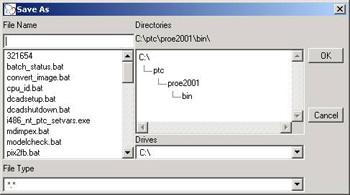
Figure 1
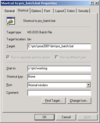
1. Create a shortcut on your desktop for Pro/BATCH found in the location
shown in Figure 1. If you do not know how to create a shortcut to this
file, do the following:
a. Open My Computer from your desktop.
b. Browse to the location of pro_batch.bat as shown in Figure 1.
c. Right-click it and select Create Shortcut.
d. Drag it out to your desktop.
2. Open the shortcut by right-clicking on it and viewing its properties.
3. Fill in the location of where your config.pro file resides, as shown in
Figure 1. You only need to complete this step once. This lets the batch file
see your config options for printing. If you fail to do this, printing will be
difficult. (You will see lots of datums, CS, thick lines, etc.)
4. Select Apply and OK.
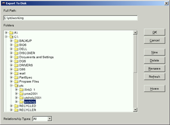
Get the files local to your hard disk
1. Create a new directory on your hard drive. This is the location where you
will export your files. I recommend not using your working directory.
2. Check out as usual from Pro/INTRALINK into a workspace. (Drawings, models,
assemblies, etc.)
3. Open your Workspace browser window and select Edit. Select All
from the pull-down menu.
4. Select Object >Export >To Disk. (See Figure 2.)
5. Select the directory you just created to which you will export. Relationship
types should be set to All and select OK.
Figure 2
Start Pro/BATCH
1. Launch Pro/BATCH via the new shortcut you have just created on your desktop.
Figure 3
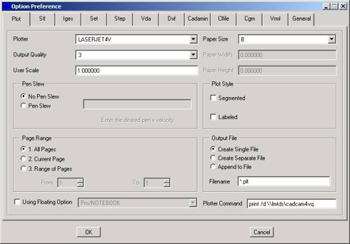
2. Go to Preferences and set the following as shown in Figure 3. This
is the configuration that will work with our laser printer. You only can
batch-plot all the drawings in the same size. (Notice the paper-size drop down.)
The plotter command line is important: print /d:\\\.
The command line for laser printing is the following: print /d:\\lmtds\cadcam4vq.
This is different for other plotting devices. (The only space that exists in the
command is between the t in print and the /.)
Figure 4
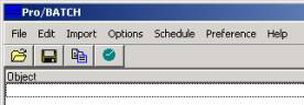
Figure 5
3. Next browse to the location of your exported files. You can do this by
selecting the black and blue paper-looking toolbar icon and add the files to the
list and Close. (Filter by file type if necessary-Drw, asm, prt.)
Figure 6
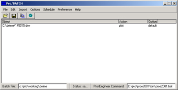
4. Fill in the Pro/E command: C:\ptc\proe2001\bin\proe2001.bat or wherever
Pro/E exists on your machine.
Figure 7
5. Select File Save. Name the batch file in the space provided and
save it. This can be reused if the exported files still exist locally.
6. Under the Schedule pull down, select Start the Task.
Figure 8
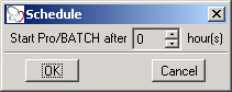
7. You can tell Pro/BATCH when to send the prints by specifying 1 hr, 2 hrs,
etc. If you type 0, the prints will send immediately.
I have used this procedure only with a laser jet printer. I am unsure how it
will work with larger plotters.

2003/03/04
Scaling in Sketcher
Since the introduction of Intent Manager, many users have struggled while
trying to modify dimensions inside Sketcher mode. This occurs when they fail to
take advantage of the Lock Scale functionality. With Lock Scale, managing and
controlling sketches is simplified and time spent changing one dimension at a
time is eliminated. To take advantage of this functionality, you must be inside
Sketcher mode. After you create a sketch, it is likely that the assigned Pro/E
dimensions are not what you require. (They are usually too large). Changing each
dimension, one at a time, can cause your sketch to fail, can make your sketch
confusing to look at and can be a tremendous hassle. To avoid the problem,
simultaneously highlight all the dimensions in the sketch. Do this by selecting
them singly or by dragging a box around all of them. The latter method is
quicker and more reliable. Once all the dimensions are highlighted in red,
right-click the mouse and select Modify from the pop-up menu. The Modify
Dimensions dialog box will appear. (See Figure 1.)
Figure 1
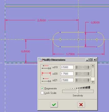
Check the Lock Scale box inside the Modify Dimensions dialog box and make a
change to the one dimension listed on the right side that you wish to change.
(See Figure 2.)
Figure 2
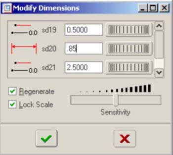
When you finish the dimension change and have selected the Lock Scale box,
select the red check mark inside the Modify Dimensions dialog box and the sketch
will regenerate. After regeneration, notice that the dimensions that you did not
change in the Modify Dimensions dialog box have maintained their scale in the
sketch.
--Submitted by Stan Balish, president and CEO, FroTime Inc, San Diego, CA
Selecting a Range of Features in Wildfire
A range of features or components can be selected to perform actions such as
suppress, delete, place on layer, etc. In previous releases, this was
accomplished by using the Range option in the menu. In Wildfire, this
functionality is available through the Search Tool. Launch the Search Tool by
selecting the icon or selecting Edit >Find. Select Options >Build
Query and select the History tab. Select the Number Radio Button,
and add two rules:
- Number is greater than or equal to < lower number >.
- Number is less than or equal to < upper number >.
When Find Now is selected, the desired range is found, and when
Apply is selected, the items are selected for operation.
--Submitted by Florin Neamtu, principal engineer for PTC technical support,
Needham, MA
A Lost Trick in Assembling Components
Here is how to move or spin a component that is being assembled free of the
assembly, and before it is fully constrained. Use the Control + Alt keys in
addition to the middle-mouse button (MMB) to spin it and use the right-mouse
button (RMB) to move it. This is a good way to get components into their proper
position and add constraints. It also works well if you require another
constraint and cannot determine the direction of that constraint. Once a
constraint is added, the part cannot be moved in a direction that would
contradict the constraint.
--Submitted by Kyle Davidson, Racar International, Anderson, IN, (765)
644-4727
Another Way to Create Text on Curved Surfaces
In addition to the method described in last month's Pro/Clues Digital Digest,
another way to create text on a curved surface, not only cylindrical surfaces,
is to use Offset or Draft Offset. This works well if you also need to
incorporate draft on the text.
Create a datum curve with the text. Then select Feature >Create >Tweak
>Offset or > Draft Offset. There are other options available to
control the feature, but I will not go into detail here. I will suggest,
however, that you avoid using Tangent and start with a small draft. Increase it
with Modify until you get the desired draft. The advantage to following this
method is that you can use it on any surface and it does not require outside
calculations
--Submitted by Kyle Davidson, Racar International, Anderson, IN, (765)
644-4727
Showing Various Mechanisms Positions Without MDX
In the Drag Dialog snapshot, the mechanism position uses the "make available in
drawing icon" to make the snapshot visible in the drawing. Snapshot the
mechanism at all the positions you wish to communicate and make them all
available in the drawing. A user without Mechanism design can view the various
mechanism states by using the Explode State menu. Use Set Current to pick
one of the mechanism snapshots.
--Submitted by Ian Turner, design application support, CSC Computer Sciences
Corp., MBDA UK Account, Stevenage, UK
2003/03/05
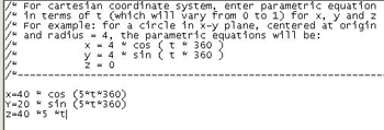
Using the Trajpar Parameter in Helical Sweep
Features
This tip is designed for Release 2001, but will work with 2000i2 as well. The
trajectory parameter, also known as trajpar, typically is used in variable
section sweep features to vary dimensions. However, the trajpar parameter also
can be used in helical sweep features to control the cross section (not
profile).
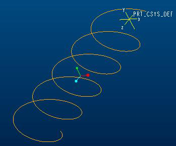
The trajpar parameter varies from 0 to 1 along the trajectory of the helical
sweep (0 at the beginning, 1 at the end).
A relation such as sd2=1+trajpar*2. (see Figure 1) would set sd2=1 at the
beginning of the sweep and 3 at the end, increasing linearly along the
trajectory. The final helical sweep would look like Figure 2.
Submitted by Florin Neamtu, senior technical support engineer for PTC
technical support, Needham, MA
Figure 1
Figure 2

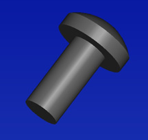
Simplify your Pro/E models
This tip is for Pro/E 2001 Build 2350. Overmodeling an object in Pro/E has a
number of disadvantages, the most damaging being unnecessary features that are
not needed to convey design intent. A common example is hardware such as screws,
nuts and fasteners. It may look cool to have your pan head cross-recess screw
modeled to exact specifications including every round and cut feature that
exists but is it necessary? These features require regeneration time. If enough
are present, the extra features may cause a decrease in your machine
performance.
If you determine that certain features of your part are not needed but might be
displayed graphically, there are a few methods you can use to accomplish this
task. One is to replace unnecessary features with datum curves. Datum curves can
be created to resemble cuts, rounds, text or protrusions that you typically
would create using normal solid features. Using the pan head screw as an
example, a fully detailed model of a pan head cross-recess screw could have
anywhere from 10 to 15 features on average. The same screw can be made with as
few as two features using datum curves to represent the cross-recess feature of
the screw. The first feature can be a simple revolved protrusion. (See Figure
1.)
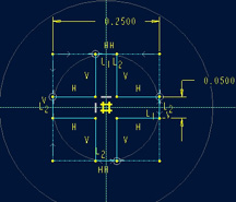
The cross-recess feature can be a projected datum curve. You can sketch the
cross-recess section on any plane or surface that is perpendicular to the axis
of the screw. Using symmetry and construction lines you can control the
cross-recess section using two dimensions. (See Figure 2.)
Select the two top surfaces that represent the top of the pan head screw.
This is where your section will be projected. Relations can then be written to
control the size of the cross-recess datum curve feature based on the head
diameter of the screw. This is useful if a family table is created for the
screw. Finally, the color of the datum curve can be set to accommodate your
specific needs using >Modify >LineStyle (this is an advantage over using
cosmetic text for the feature). The final simplified part with two features
should appear as shown below. (See Figure 3.)

Submitted by Stan Balish, president and chief executive officer, FroTime
Inc., San Diego, CA
No Online Help For Pro/MECHANICA?
PROBLEM: Have you ever been in MECHANICA Integrated Mode and tried to get
MECHANICA help through the HELP pull-down menu? If so, then you have discovered
that none of the MECHANICA manuals are listed in the Contents and Index
selection. Although you can access menu-specific MECHANICA help using the
right-mouse button on any given MECHANICA menu-pick, you cannot access the
top-level index area of MECHANICA's Help page.
EXPLANATION: When installing MECHANICA you tell it where the help
directory path is, but this is only used for the Independent Mode. With
Pro/ENGINEER Version 2001 and lower you are not able to access the MECHANICA
Help index page from within Pro/ENGINEER. Here's a method to make the MECHANICA
Help index page available while in the Integrated Mode:
PROCEDURE: Open the browser you use with your Pro/ENGINEER software.
Type the path to your Relxxhelp.htm file in the MECHANICA directory. An example
is given below for rev. 2001:
EXAMPLE PATH: D:\Program Files\promech2001\html\usascii\promec\Rel23help.htm
This is the top-level index page for MECHANICA Help. Once the page is
loaded, add it to your Favorite location (bookmark it) in the browser.
IMPLEMENTATION: To use this tip starting with a fresh Pro/ENGINEER
session, you do not have to be in the MECHANICA menu. At any time, click the
Help pull-down menu and select Contents and Index. Select the new
MECHANICA Index link in your Favorites menu after the browser comes up.
Alternatively, open your browser apart from Pro/ENGINEER and select the
MECHANICA Index link.
I do not know whether this will be necessary within Pro/ENGINEER Wildfire.
Submitted by Randy Speed, president, Speed Consulting, Waxahachie, Texas.
Speed is a member of the Pro/E Digital Digest advisory board. To read his
bio,
click here.
Solving the Problem of Showing Cosmetics on
Drawings
You have a drawing with a dozen views. There are some cosmetic features that you
have accidentally turned off in these views. You would think it would be a
simple task to use the Show/Erase dialog box and turn them back on. No such
luck. The detail item button for cosmetic features is grayed out in the show
mode. To solve this problem, turn off the preview option in the Show/Erase
dialog box. Show cosmetics does not function with preview. To turn preview off,
you must select the preview tab from the Show/Erase dialog box, make sure a
button other than cosmetic is activated, and un-check the preview box.
Gunnar B Hansen, engineer, damixa, Denmark
Avoiding Linking Problems with Archived Files
Our company has worked with Pro/E for a long time and it has archived many old
designs. Occasionally, linking problems arise when we try to retrieve the old
designs that link to other files that are archived. This can be particularly
frustrating when opening large assemblies that no longer can find files,
especially because our early system did not document what some CAD models
represented. One way to mitigate this problem is to choose the menu option to
open a simplified representation of the large assembly even if you do not know
what simplified representations exist in the model. When the list appears,
select the option to create a new simplified representation. All of the model
names in the assembly are shown without regenerating any geometry. You can
determine from the model names in the assembly whether or not it is the assembly
you are seeking, and if so you can be sure that all of the models are unarchived
before wasting time trying to regenerate the model geometry.
Submitted by Randy Palmer, mechanical design engineer, Government Systems,
Isothermal Systems Research, Clarkston, WA
More Ideas on Good Sketching Practice-Comment on
Vol. I, Issue 1, Pro Clues 2
I found Kim Cheatham's article, "Learning to sketch with Intent Manager,"
useful, but I have a couple of reservations concerning the technique. One
concern I have is the lack of attention to geometric constraints, which can
greatly reduce the number of dimensional constraints required. The method I
recommend follows:
As you sketch, points will snap to existing entities and geometric relationships
will be applied automatically according to where you move your cursor. This is
the Intent Manager making assumptions about your Design Intent. This process is
useful and you should search for the constraints. If you do not want the
constraint to be applied, move your cursor to a position to where it is not
applied and then reposition the point or entity.
Here are some steps to achieve good sketching practices:
Step 1: Use the Sketcher grid and zoom in/out to make the graphics area
the same size as your intended sketch. This will avoid problematic bit-by-bit
scaling through modification of dimensions in the sketch once it is completed.
Large movements of entities will result in extreme distortion of the sketch.
Step 2: Using Lines and Arcs (rather than trimmed circles and squares),
start from one point and create the sketch in a continuous line. Trimming
circles and squares can result in disconnected end points. This causes open
loops that are hard to fix. You also are more likely to create lines on top of
lines, which are difficult to detect. Starting from one point and switching from
line to arc as you work around the loop ensures good connections.
Step 3: Create the sketch to the correct proportions to avoid resizing
work. Drag points and entities to approximately reshape the geometry.
Step 4: Apply geometric constraints. Connect the sketch to the sketching
references and use geometric constraints before dimensional constraints to fix
its shape and proportions. This will minimize the number of dimensional
constraints. The common constraints you will use are tangency and coincidence.
Step 5: Apply dimensional constraints. It is a good practice to try to
leave the sketch with no gray, weak dimensions. This ensures all dimensions have
been considered and checked.
Step 6: Modify the dimensions. Using the pick icon, double-click a
dimension to modify it. Also, using the pick icon you can drag a box around your
dimensions to select them and then pick the modify icon to list the dimensions
for easy modification. Uncheck the regenerate option because it may cause
distortion as each dimension is updated when you make changes.
Step 7: Resolve sketch failures. If the sketch fails it is most commonly
due either to disconnection between points causing an open loop-look for weak
dimensions of zero or because you have lines on top of lines.
This last issue is the main advantage of creating the sketched loop an entity at
a time, continuing from the end point of the previous entity using line and arc
segments. This method of creating robust sketches is by no means the only way.
There are always exceptions that everyone develops in their own techniques, but
I have found this to be a good starting point. Creating robust and successful
sketches as the basis of most of the common Pro/E features is a crucial step on
the way to a successful model.
Sean Kerslake, department design and technology, Loughborough University, UK
More Help Needed on Helical Springs Clue-Comment on
Vol. I, Issue 2, Pro Clues 1
I followed the clue, "Helical Springs Around Non-Linear Trajectories" by Florin
Neamtu in the Vol I, Issue 2 edition of Pro/Clues Digitial Digest, and I
am unable to create the helical spring around non-linear trajectories. Please
advise me.
Harsha Mallikarjuna Thumbaraguddi, design engineer, Praveen CAD Systems,
Bellary, Karnataka, India
It's Not That Easy-Comment on
Vol. I, Issue 2, Pro Clues 2
Changing the setting of the new_parameter_ui option may not be as easy as
the instructions indicated. This option was not even listed under Current
Session. Once in Utilities >Options, I had to click the Find
button, type in new_parameter_ui, hit Enter and double-click on it
when it appeared in the lower window. Only then was I allowed to change the
setting from no to yes. In the process of figuring this out, I
also found the new_relation_ui option, which apparently performs a
similar function for a relations list. It also is hidden and must be changed
with the process I outlined.
Jon Smedley, senior product designer, AXXION Group, El Paso, TX
Further Questions-Comment on
Vol. I, Issue 1, Pro Clues 1
I have a further question regarding Pro/Clues 1 "File Open Dialog Features." How
do I save these settings so they are always there the next time I open a file?
If the settings cannot be saved, is it quicker to alt+tab back to my workspace
and see what I need to see?
Scott E. Szabo, manufacturing engineer, New Product Development,
Ingersoll-Rand Company, Blaw-Knox Division, Mattoon, IL
Answer to Vol. I, Issue 1, Pro Clues 1 Question
No, the settings can not be saved. In my opinion it is faster to use the file
open dialog box instead of alt+tab. But it may be faster for you.
Submitted by Stan Balish, president and chief executive officer, FroTime Inc.
in San Diego, CA
2003/04/11
Be Flexible in Wildfire
Flexible Components is a new function in Pro/ENGINEER Wildfire that gives users
added capabilities for assembly management. The Make Flexible command allows
users to change solid objects into flexible objects existing in different states
inside an assembly. Each occurrence of the component can have a different
flexibility assigned to it, and it will only show up as one BOM item. Having
this capability eliminates the need for multiple unique object numbers for a
single object displayed in different states. Prior to Wildfire, it was necessary
to create unique objects or family tables when attempting to display the same
spring in different states of compression in the same assembly. This added extra
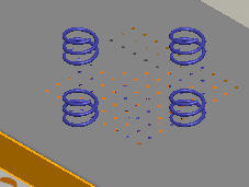
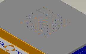
items to the BOM and required a manual change to correct. Figure 1 shows
five uncompressed springs assembled to holes in a circular housing. The four
springs around the outer surface of the housing are sitting on washers that are
located in the middle of each hole.
Figure 1
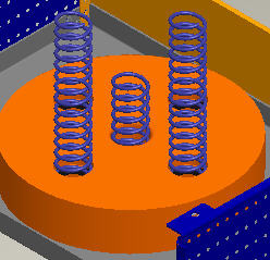
The center spring is located in a hole that has no washer, so it rests on the
surface of the chassis to which the housing is assembled. When the cover of the
chassis is installed, the four springs will protrude through the top of the
cover while the fifth spring (fully uncompressed) just touches the inside of the
top cover. (See Figure 2.)
Figure 2
Compressing the four springs that are assembled to the outer holes on the
housing so that they just touch the inside of the top cover, can be accomplished
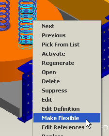
in Wildfire by making the springs "Flexible" components. Highlight one of the
springs that you wish to compress and click your right-mouse button. Select
Make Flexible from the pop-up menu. (See Figure 3.)
Figure 3
The Varied Items dialog box will appear. (See Figure 4.)
Figure 4
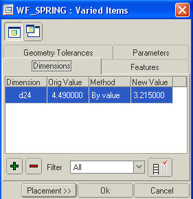
Select the green add button and use the Search Tool to find the
dimension in the spring that will allow it to be compressed. Select Apply
and select OK from the Select box. The dimension you selected will be
visible in the Varied Items box. (See Figure 5.)
Figure 5
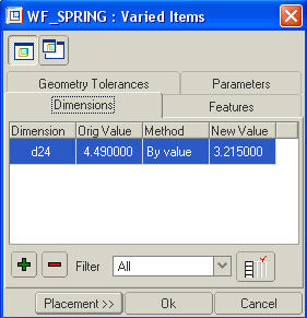
Change New Value to allow the spring to just touch the inside of the top
cover and select Placement from the Varied Items dialog box. The
Component Placement dialog box will appear with a new button called Define
Flexibility. This button allows you to go back and modify the flexibility values
(varied items) of the spring. Select OK from the Component Placement
dialog box to complete the operation. The springs should be completely inside
the top cover, as shown in Figure 6.
Figure 6
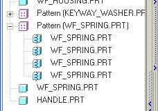
Inside the model tree, the four springs will have a new icon attached to them
indicating that they are flexible components. (See Figure 7.)
Figure 7
--Submitted by Stan Balish, president and chief executive officer, FroTime
Inc., San Diego, CA
How to Flatten a Harness Without the Network
(This tip can be applied in Wildfire in the Harness-MFG module.)
In previous releases, harness networks were flattened automatically with the
wires, cables or bundles in a flattened harness. The only way to remove the
network was to blank on a layer.
In Pro/ENGINEER Wildfire, the config.pro option "fan_with_network" has been
added and may be set to NO (default is YES) to exclude the network
from being flattened.
--Submitted by Florin Neamtu, principal engineer, PTC technical support,
Needham, MA
Determine What Materials to Use
When parts are in the early development stages, it is not always clear which
material to use. For example, 50 percent long glass polypropylene has a
different performance characteristic and density than 20 percent short glass.
Rather than modifying the Pro/ENGINEER part's density every time you want to
look at its total weight, you can write a relation to maintain as many options
as you wish. See below:
weight_material_1 = density * mp_volume("")
weight_material_2 = density * mp_volume("")
Substitute the material name and density values as needed. The "weight_material_*"
parameter then can be displayed as a parametric note on a drawing or used for
further calculations.
--Submitted by Steven J. Frey, vice president, Universal Parametrics, Inc.,
Ann Arbor, MI
Show a Mechanism Position on a Drawing
Under Drag Dialog, snapshot the mechanism position. Use the
make-available-in-drawing icon to make the snapshot visible in the drawing.
Create a new view or modify an existing view. Set the type as exploded. The
mechanism snapshots will be listed as an exploded state.
--Submitted by Ian Turner, design application support, CSC, MBDA UK Account,
Stevenage, UK
Drawing Snap Lines
Use snap lines to expedite drawing cleaning. A snap line is a line that shows up
on the screen but not on the printed drawing. It allows you to line up balloons,
notes or any draft entities that can be moved using the normal move command.
When an entity is selected and moved near the snap line, it snaps to it.
The moved entity will change colors when it is attached to the snap line. By
using the snap line, balloons can be lined up perfectly straight. The figure
below shows several balloons lined up on two snap lines.
Snap lines can be defined on individual drawings to locate dimensions, notes,
geometric tolerances, symbols and surface finishes. The system positions the
snap lines relative to the view outline, a selected model edge or datum plane.
After you place an item on a snap line, the item moves if the grid line moves
(such as when the view outline expands).
When placing and locating items on snap lines, keep the following two points in
mind:
- When you move an item onto one snap line, its color changes to magenta. If
you set the location by pressing the left-mouse button, the item snaps to the
snap line. Until you move the item again, the snap line determines its
location.
- If you move an item onto the intersection of two snap lines, the system
highlights one of the lines in red. If it snaps that item to more than one set
of snap lines at that location, you can navigate all possible sets using the
SEL SNAP LINE menu. When you choose Accept, the system locates the item on the
intersection of the two snap lines. When you move either snap line, the item
moves with it.
To Create a Snap Line:
- Select Insert >Snap Line on the menu bar.
- On the Menu Manager, do one of the following:
--Ed Muirhead, CAD systems administrator, Aberdeen, Scotland, UK.
2003/04/18
Q1- Vol. III, Issue 13
I am trying to model the shin guards (shown below) in Pro/ENGINEER, but I am
having trouble getting the shape to be correct. Can you recommend any advanced
tutorials or other training guides to help me solve this modeling problem?
--Andrew Walter, engineering student, Australian National University,
Canberra, ACT Australia
A1.1- Vol. III, Issue 13
The profile of the skin guard you show on the picture seems quite complex. It is
better to first digitize it using a laser digitizer or CMM. Afterward, bring the
digitized data into Pro/E.
--Yasir Arfeen, CAD/CAM engineer, OJ Pvt. Ltd., Karachi, Pakistan
A1.2- Vol. III, Issue 13
The best tutorials at student rates can be found at
www.frotime.com.
--G. Alexander Korentis, mechanical/biomedical engineer, QCI Engineering,
University of Connecticut, biomedical engineering doctoral student, Storrs, CT
A1.3- Vol. III, Issue 13
Take the "Advanced Surfacing Training" course offered by PTC or Rand.
--Chris Boyer, manager of product creation, Freudenberg Household Products
LP, Northlake, IL
A1.4- Vol. III, Issue 13
You might try looking into medical archives. If an FTP site exists for your
software, you may find proven applications there.
--Craig D. Skogerson, Indio, CA
Q2- Vol. III, Issue 13
I just received Pro/ENGINEER Wildfire and I am concerned about its stability. In
the past, I have heard it was wise to wait a few months before installing new
versions. Has anyone had problems with Wildfire and would you recommend I wait
until any possible bugs are worked out?
--Pascal Normand, designer, research and development, Industrial Handling
Division, IPL Inc., St-Damien, Quebec, Canada
A2.1- Vol. III, Issue 13
I've been using Wildfire for about a month and I have not come across any bugs
yet. I do stress yet. I have found it much better and easier to use than
R2001 once you get to know where everything is. An important addition is the
Menu Mapper under the Help menu. To find out how to do something in Wildfire,
open the Menu Mapper. The Menu Mapper shows an R2001 screen with the old-style
menu layout. After you run through the R2001 way of executing the command, using
the R2001 menus shown, the Menu Mapper will show you how to do it in Wildfire.
It is an excellent tool.
--Jeff Taylor, mechanical production engineer, Imagination Technologies Ltd.,
London, UK
A2.2- Vol. III, Issue 13
I installed Wildfire and just did my first real rush job with it. I took nine
hours nonstop and a large thermos of coffee. But I got it done. This was the
first time I used it. I have had no training on it. That speaks to its usability
and the fact that the interface has not changed a lot from the previous version.
However, Wildfire crashed four times doing routine tasks. Thankfully, no
critical steps were lost, and I was able to carry on. But it is definitely not
yet stable.
--Christopher J. Purcell, defense research and development, Canada Atlantic,
Dartmouth NS, Canada
A2.3- Vol. III, Issue 13
Wildfire does not work with Pro/INTRALINK.
--Tom Hargrove, fusion energy division, Oak Ridge National Laboratory, Oak
Ridge, TN
A2.4- Vol. III, Issue 13
You are right. Often it is better to wait for some builds after the first
production edition of a new Pro/E release. I have not tried Wildfire yet, but
I'll wait at least a couple of months before using it in a production
environment.
--Luca Armellin, mechanical engineer, Metelli SpA, Brescia, Italy
More Answers to Previous Questions
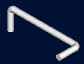
Q1- Vol. III, Issue 12
I have modeled a rod with two bends on two different planes. How do I unbend the
rod shown in the image below?
--Herb Spaulding, product engineer, Miller Industries, Ooltewah, TN
A1.1- Vol. III, Issue 12
Create a datum curve that follows the path you want. If it is a 2D path you want
to follow, you have to use the 2 Projections option in the Curve menu. Select
Insert >Datum >Curve and choose 2 Projections. If you choose two
datums at right angles to each other, they will create a datum curve where the
two intersect. You can then create a sweep. Select Create >Protrusion >Sweep
and choose Select Traj. Select the datum curve you have just selected and
sketch a round section. This technique can also be used to create sweeped pipes
in assemblies.
--Brian Middlemore, CAD support engineer, NCR Ltd., Dundee, Tayside, Scotland
Bar
Datum curve

A1.2- Vol. III, Issue 12
If you have modeled the rod with a toroidal bend tweak and you want to obtain a
straight workpiece, suppress the toroidal features.
--Zachary Popov, mechanical engineer, Technical University, Varna, Bulgaria
Q2- Vol. III, Issue 12
As of Pro/WILDFIRE, the internal datum plane, aka "on-the-fly" created datum
plane, functionality is removed. I am wondering if this will impair model
building?
--Alexander Fabre, B. Sc. M. E., Avalon Technology Stockholm AB, Sweden
A2.1- Vol. III, Issue 12
This functionality resides within the feature creation. While creating the
feature, click on the pause button at the bottom right of the screen. (It is
next to the preview button.) Create the necessary axes, planes, points etc, and
click on the pause button to continue building the feature. (Planes, axes,
points, etc. on the "fly").
--Roman Panov, MCAD application specialist, Engineering Data Resources AS,
Norway
A2.2- Vol. III, Issue 12
The "Make Datum" command is not necessarily removed, it has been restructured.
An "on-the-fly" datum still can be created by means of the same menu option for
creating a datum. The difference in Wildfire is that the "on-the-fly" datum
plane is an actual feature in the Model Tree and can be selected for reference
when creating other features. So "on-the-fly" datums are now more useful. The
only impairment is that users accustomed to the old menu selection have to learn
Wildfire's dashboard-style menu structure, which is easy to learn.
--Wes Gerber, mechanical design engineer, ITT Industries,
Aerospace/Communications Division, Fort Wayne, IN
A2.3- Vol. III, Issue 12
The internal datum plane functionality is not removed. It is accessed
differently. If you wish to create a datum on the fly, use the same icons or
menu picks as you would when creating "visible" datums. Datums created during
feature creation are listed in the model tree, but are automatically hidden and
grouped with the feature being created. In most cases the feature you are
creating - such as an extruded protrusion - will grab the plane you create and
use it for the sketching plane. If Wildfire does not select the created plane
automatically, then you can select it yourself. The important thing to note is
that on-the-fly datums are still with us.
--Kellie Wheatcroft, mechanical engineer, Smart Design, Perth, Western
Australia