|
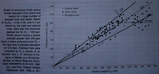
變動負荷 Introduction A fatigue failure begins with a small crack . The initial is so minute that it can not be detected by the naked eye and is even quite difficult to locate in a Magnaflux or x-ray inspection .The crack will develop at a point of discontinuity in the material, such as a change in cross section , a keyway , or a hole . less obvious points at which fatigue failures are likely to begin are inspection or stamp marks , internal cracks , or even irregularities caused by machining. 疲勞破壞(fatigue failure)-當元件承受循環負荷作用下,元件不連續處會產生裂縫,在高張應力作用下,裂縫會造成擴展,而使斷面積縮減,經過數次循環作用下,斷面淨面積減至無法承受當時之負荷,即造成突然斷裂,此謂之. 疲勞強度(Fatigue Strength)-材料欲達到或超過某一循環壽命N其所能承受的最大完全反覆應力值,即謂之對應於該循環壽命N之疲勞強度. 疲勞限(Fatigue limit or Endurance Limit)-材料(元件)欲達到無窮壽命,其所能承受的最大完全反覆應力值. The endurance limit The determinatin of endurance limits by fatigue is now routine , though a lengthy procedure. Generally, Stress testing is preferred to strain testing for endurance limits . By plotting these as in Fig . it is possible to see whether there is any correlation between the two sets of results . The graph appears to suggest that the endurance limit ranges from about 40 -60 percent of the tensile strength for steel up to about 200 kpsi (1400 Mpa) . Beginning at about Sut = 200 Kpsi , the scatter appears to increase , but the trend seems to level off, as suggested by the dashed horizontal line at S'e= 100 kpsi (700 Mpa) .
Mischke has analyzed a great deal of actual test data from several sources and concluded that endurance limit can. indeed, be related to tensile strength. For steels.
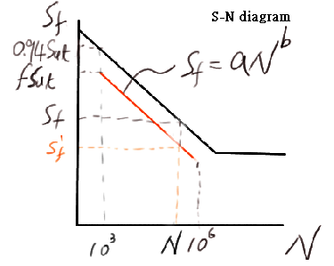
The Fatigue Strength N Sf 103
fSut 106 Se' ∵Sf=aNb ∴log Sf=log a + b log N As N=103 ,Sf= fSut->log(fSut)=log a + 3b-----------------(1) As N=106 ,Sf=Se' ->log Se'=log a + 6b---------------------(2) (1) *2 - (2) 2*log(fSut)-log Se'=log a a= (fSut)2 / Se' (1)-(2) log(fSut)--log Se'=-3b b=-(1/3) log (fSut/ Se') Endurance-Limit Modifying Factors Se=ka kb kc kd ke Se' Se= Endurane limit of mechanical element Se'=Endurance limit of test specimen ka=surface factor kb=size factor kc=load factor kd=temperature factor ke=miscellaneous-effects factor surface factor ka ka = a Sutb
Size Factor kb The results for bending and torsion be expressed as
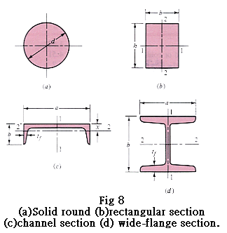
For axial loading there is no size effect.Therefore, use kb=1 不回轉樑如所受最大應力0.95以上所具有之體積與回轉樑相同,則有相同之尺寸修正因素. A0.95=pi/4 *[d2-(0.95d)2]=0.0766d2 圓形不迴轉樑 A0.95=∫0.475d 0.5d (√(d2/4-x2
dx))=0.0105d2 0.0105d2=0.0766de2 de=0.37d 長方形不迴轉樑 A0.95=0.05bh 0.05bh=0.0766de2 de=0.808(bh)1/2 These section are shown in Fig together with a channel and a wide-flange or I-beam section. For the channel,
The 95 percent stress area for the wide flange is
Load Factor kc kc=α*Sutβ LN(1,C)
Temperature Factor kd kd=ST/SRT
kd=[0.975+0.432(10-3)tf-0.115(10-5)tf2+0.104(10-8)tf3+0.595(10-12)tf4]LN(1,0.11) NOTCH SENSITIVITY Notch sensitivity q q=(Kf-1) /(Kt-1) Kt為理論(或幾何形狀)應力集中因素,疲勞應力-集中因素Kf. 修正Neuber公式如下: Kf=(Kt*LN(1,Ckf))/(1+((2/√r)*(Kt-1)*√a/Kt)) Kf:對數常態分佈. r:缺口半徑. √a為對應於平均抗拉強度Sut‾的函數.
Kf=1+(Kt-1)/(1+√(a/r))-------------------------(28) q=1/(1+√(a/r))------------------------------------(29) √a=0.220353-0.275605(10-2)Sut‾+0.113449(10-4)(Sut‾)2-0.247328(10-7)(Sut‾)3--------(30) kt:形狀,負重方式而與材質無關. kf=(有缺口試桿之最大應力)/(無缺口試桿之最大應力) σmax=kf*σ0 σ0 :公稱應力. 如想將(28)與(29)式應用在低合金鋼扭轉上,可將(30)中的平均極限抗拉強度加大20kpsi然後使用計算√a之值. 註:合金鋼分類下 1.低合金鋼:特別合金元素之和少於8.0%. 2.高合金鋼:特別合金元素之和高於8.0%. Fluctuating Stresses
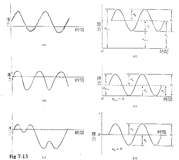
Fig 7-13 某些應力時間關係:(a)具有高頻率波紋的波動應力(b)與(c)非正弦波型波動應力(d)正弦波型波動應力(e)覆變應力(f)完全交變正弦波型應力.
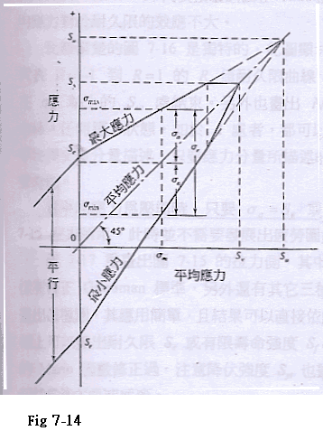
Fig 7-14 修正Goodman圖,其中顯示一特定平均應力的所有應力分量所有強度與極限值.
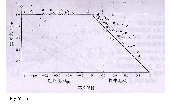
Fig 7-15 拉伸與壓縮區域內的平均應力疲勞損壞圖.利用平均強度與抗拉強度之比Sm/Sut,平均強度與抗壓強度之比Sm/Suc及強度振幅與耐久線之比Sa/Se,即可畫出各種鋼的實驗結果.
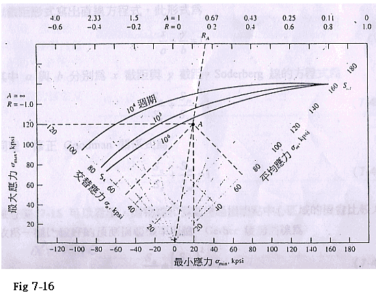
Fig 7-16 針對AISI 4340鋼畫出的主疲勞圖. σm=(σmax+σmin)/2 σa=(σmax-σmin)/2 σm:平均應力. σa=應力振幅. 當平均應力為壓縮時.只要σa=Se或σm=Syc,就會發生損壞.
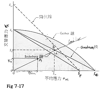
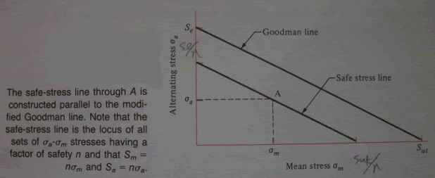
Fig 7-17 顯示出各種損壞標準的疲勞圖.對於各標準而言,在個別曲線上或外面的點表示損壞,例如Goodman線上的某一點A顯示σm的極限值強度Sm和σa(與σm成對)的極限值強度Sa的對照關係. Soderberg方程式如下 Sa/Se+Sm/Syt=1--------------------(40) 修正Goodman方程式如下 Sa/Se+Sm/Sut=1--------------------(41) Gerber疲勞曲線方程式如下 Sa/Se+(Sm/Sut)2=1--------------------(42) 畸變能橢圓曲線方程式如下 (Sa/Se)2+(Sm/Sut)2=1--------------------(43) Langer 單次-週期-降伏疲勞曲線方程式如下 Sa/Syt+Sm/Syt=1--------------------(44) The stresses
The modified Goodman relation is
The Gerber equation is
Fig . Safe-stress line 表面疲勞強度-當兩圓柱受一中心負荷作用之磨潤試驗接觸點因受力而形成一小補釘(patch),滾動後會因外力解除而恢復原形,且再受力而變形,如此變形恢復而成一循環,如經歷了108循環而表面如無任何表面疲勞跡象,則稱此小補釘中心點所承受的最大壓力為表面疲勞強度. 設計者的疲勞圖 設計應力狀態以σa',σm'表之,及損壞狀態以Sa,Sm表示二者在比較時,可以在損壞狀況時,分別出可用狀況而得到數據化的邊界值(Margin)所有這些均可在平面上畫出來,而使檢驗計畫變得簡單,且由於圖形明顯可見,幾何思考及推論甚為有用.
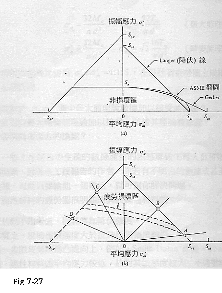
Fig 7-27 設計者疲勞圖(a)本身(b)加上數條負載線,適合判別損壞是來自疲勞或單次-週期的降伏.虛線疲勞線為一個區域. 脆性材料的疲勞圖異於延性材料處如下
設計者最常用到的範圍為-Sut≦σm≦Sut,在第一象限軌跡為Good-man,Smith-Dolan,或某些介於二者之間,在第二象限使用為一直線,且介於此區域於-Sut,Sut與O,Se之間,其式為 Sa=Se+[Se/Sut-1] -Sut≦Sm≦0 (鑄鐵) | ||||||||||||||||||||||||||||||||||||||||||||||||||||||||||||||||||||||||||||||||||||||||||||||||||||||||||||||||||||||||||||||||||||||||||||||||||||||||||||||||||||||||
網內資料: